
Honeycomb composite silicon carbide mirrors and structures

a silicon carbide mirror and honeycomb technology, applied in the field of light weight silicon carbide composite mirrors, can solve the problems of limited hb-cesic components, large projects that take a bit longer, and high complexity, and achieve the maximum size of hb-cesic components only limited

Inactive Publication Date: 2011-09-15
FANTOM MATERIALS INC
View PDF7 Cites 35 Cited by
  • Summary
  • Abstract
  • Description
  • Claims
  • Application Information

AI Technical Summary

Benefits of technology

The present invention offers thin but strong silicon carbide composites that can be used for reflecting light. This innovation also includes methods on how these mirrors can be made.

Problems solved by technology

The technical problem addressed in this patent is how to make high quality ceramic materials like siphon carburized composites (SiCMC), without having to perform expensive mechanical steps after production.

Method used


Image

  • Honeycomb composite silicon carbide mirrors and structures
  • Honeycomb composite silicon carbide mirrors and structures

Examples


Embodiment Construction

[0022]The primary purpose of this invention is to manufacture ultra-low-cost precision optical systems for very large x-ray, UV / optical or infrared telescopes. Potential solutions include but are not limited to direct precision machining, rapid optical fabrication, slumping or replication technologies to manufacture 1 to 2 meter (or larger) precision quality mirror or lens segments (either normal incidence for UV / optical / infrared or grazing incidence for x-ray).

[0023]One of the major problems perceived for conventional silicon carbide mirrors is the cost associated with machining, light-weighting and polishing the mirrors. Indeed these processes are labor, schedule, risk and cost drivers. Applicants have created and demonstrated a new silicon carbide material that overcomes these cost drivers. The new material achieves light-weighting of 92% relative to bulk material and net production cost on the order of $38,000 per square meter (unpolished) which is much less than the $1 million ...


PUM

PropertyMeasurementUnit
Shapeaaaaaaaaaa

Abstract

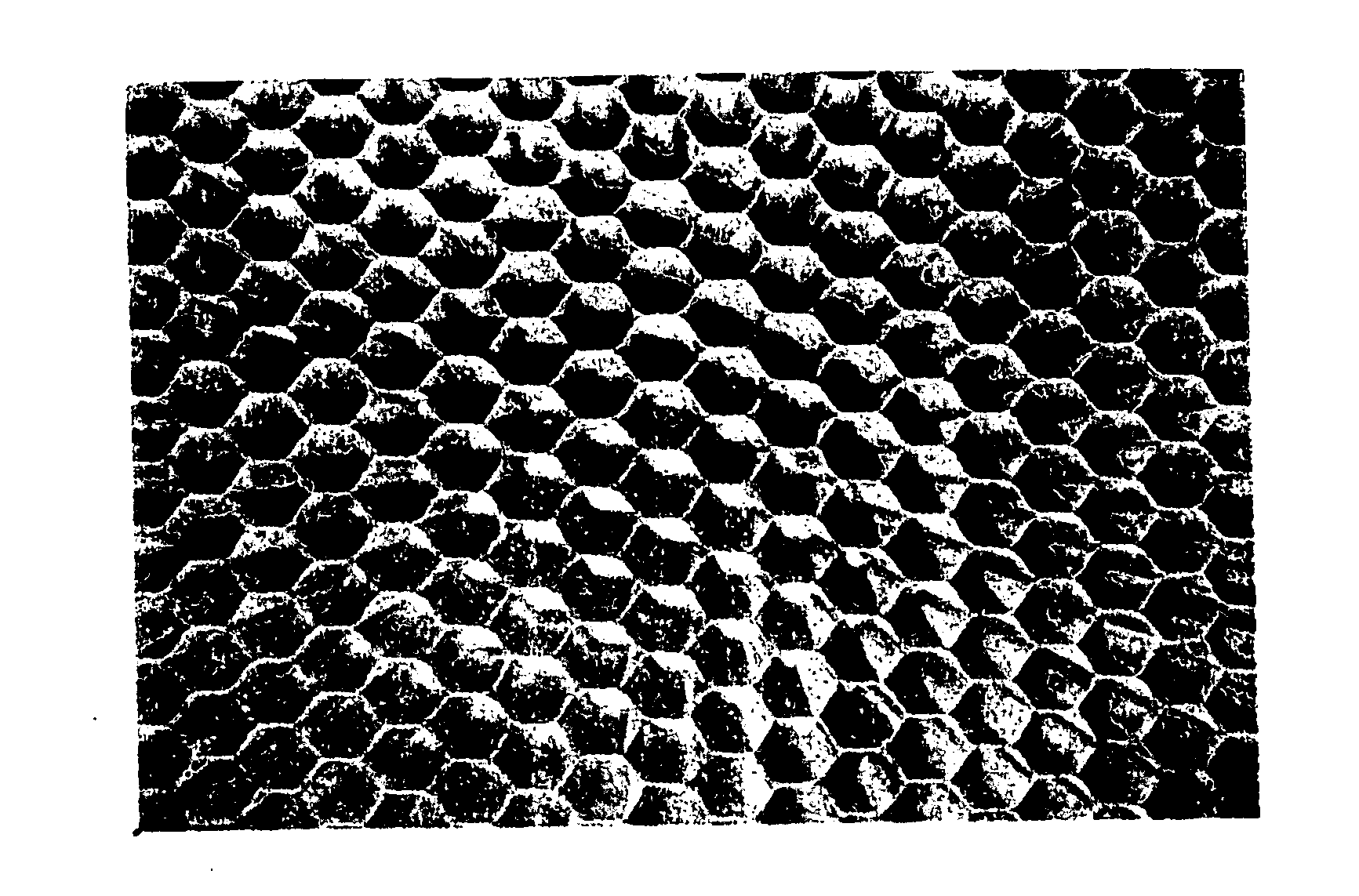
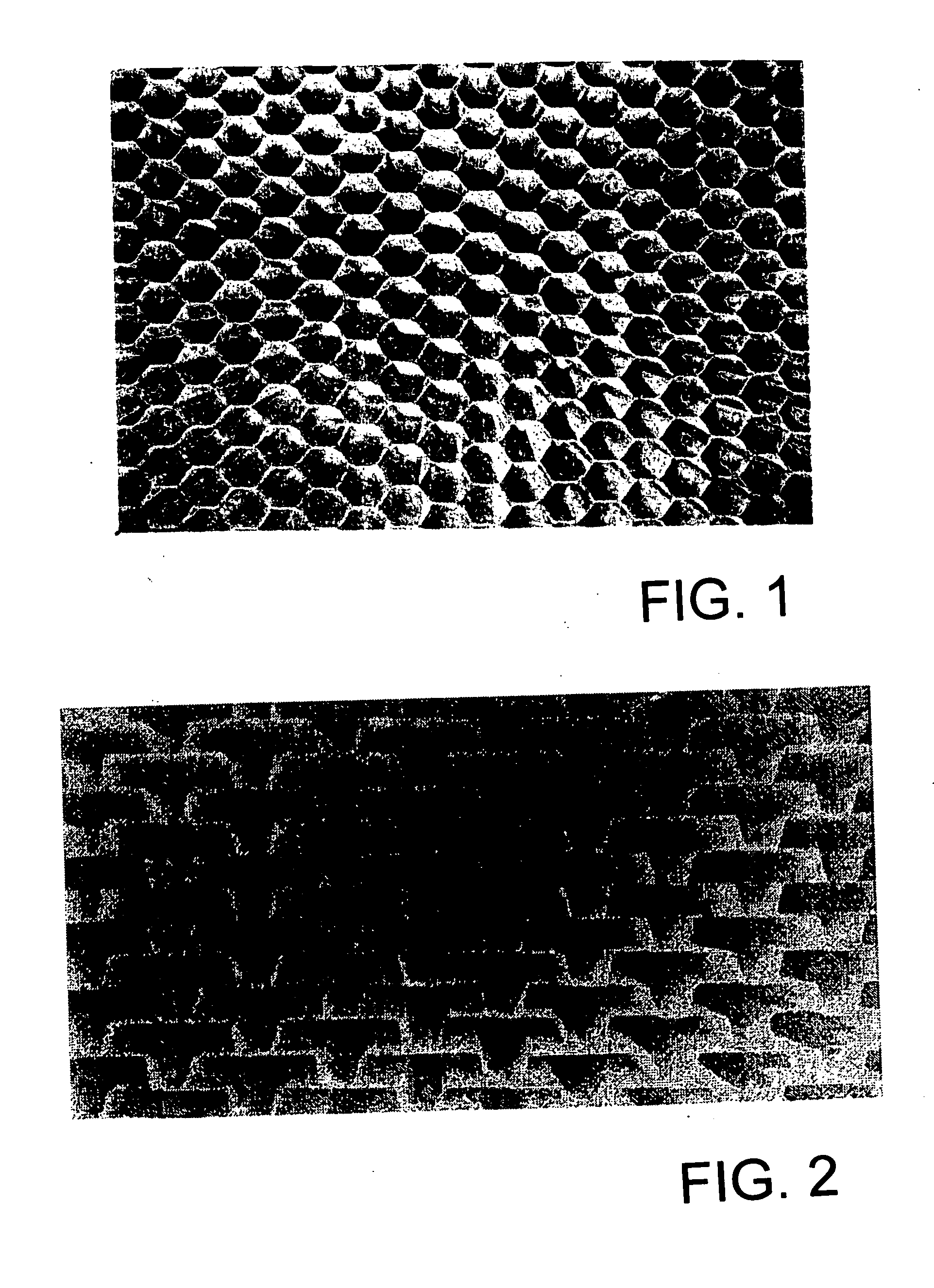
Honeycomb silicon carbide composite mirrors and a method of making the mirrors. In a preferred embodiment the mirror is made from a carbon fiber preform molded into a honeycomb shape using a rigid mold. The carbon fiber honeycomb is densified using polymer infiltration pyrolysis or reaction with liquid silicon. A chemical vapor deposited or chemical vapor composite process is utilized to deposit a polishable silicon or silicon carbide cladding on the honey comb structure. Alternatively, the cladding may be replaced by a free standing replicated CVC SiC facesheet that is bonded to the honeycomb.

Description


Claims


Application Information

Patent Timeline
Owner FANTOM MATERIALS INC
Learn More