
Lighting apparatus and lighting control method for a closed-circuit television camera, and lighting control system interlocked with the closed-circuit television camera

a technology of lighting control system and closed-circuit television, which is applied in the direction of closed-circuit television system, color television details, television systems, etc., can solve the problems of not disclosing the light control technique, the prior art is limited for still images, and the difficulty in obtaining the accurate clock signal

Inactive Publication Date: 2011-09-15
AMMON TECK
View PDF3 Cites 3 Cited by
  • Summary
  • Abstract
  • Description
  • Claims
  • Application Information

AI Technical Summary

Benefits of technology

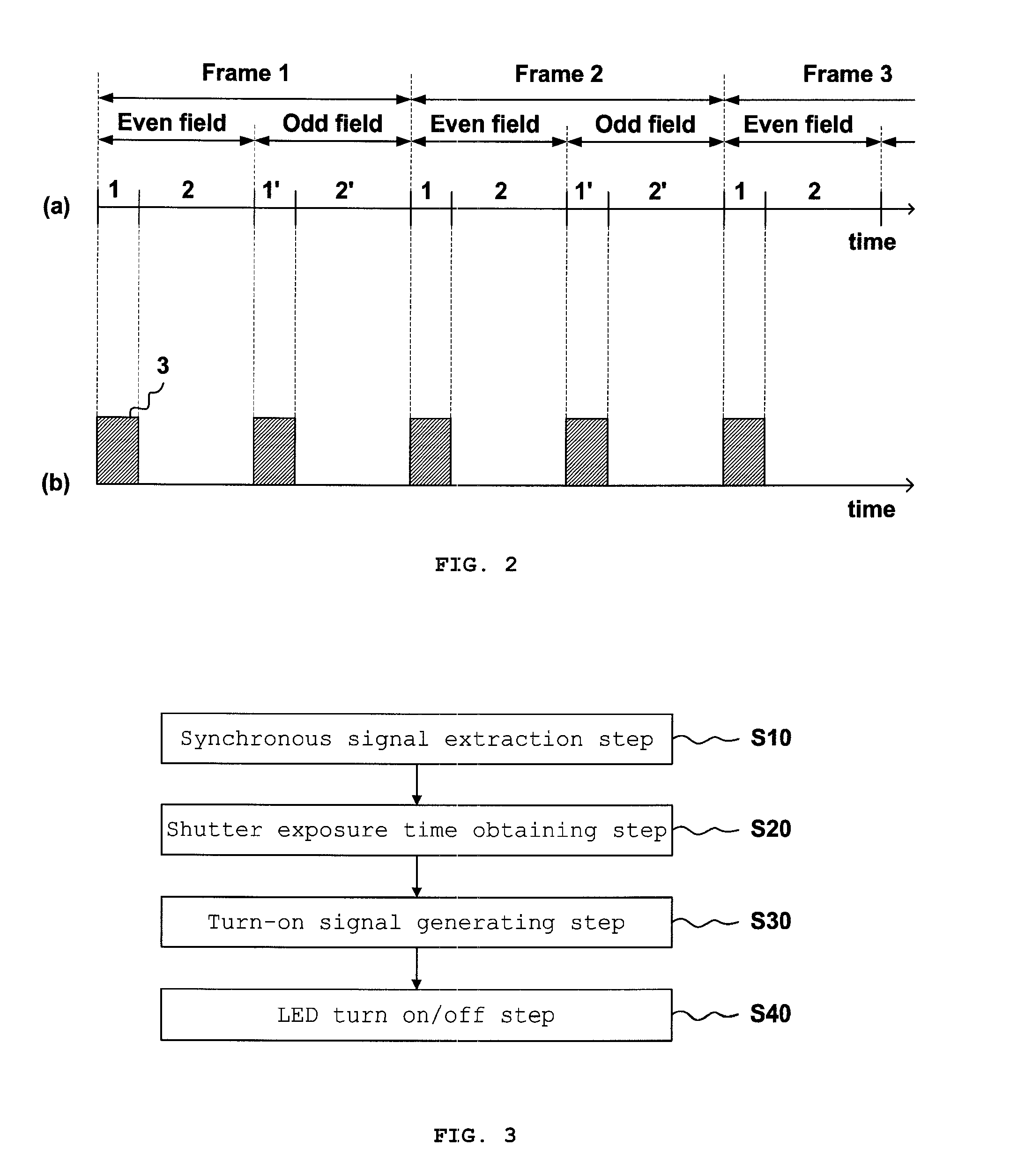
[0017]As described above the present invention is advantageous to exactly synchronize the turn-on period with the open period of the shutter because the turn-on signal is generated on the basis of the synchronous signal output by video signal and to adjust the pulse width of the turn-on signal corresponding to the turn-on period.
[0018]Further the present invention is advantageous to save the power of lights (300) which light the image area of camera, because a plurality of lights (300) installed on the area of image with camera can be synchronized with the movement of the camera shutter by local area communication.
[0019]Furthermore the present invention is advantageous to control for adjusting the turn-on time of a light and the open time of camera shutter by sensing the image sensitivity acquired in the sensitivity information acquisition unit (131) even if the turn-on time of lights and the open time of the camera shutter are not matched on initial driving.

Problems solved by technology

However, the said prior art is limited for capturing still images and does not disclose a light controlling technique for capturing moving images requested in a closed-circuit television system.
However, the said prior art should be installed a continually operating type m-PD (Photo Diode) to detect the lights and has a difficulty in obtaining the accurate clock signal because of measurement errors occurred in m-PD itself and errors in process of clock extracting.
In addition, it is difficult to synchronize the clock signal with the turn-on period for the delay time lapsed in process of extracting clock signal, and particularly if the open period of the camera shutter is to be synchronized according to the turn-on period of diode, it could not be captured the images with the requested quality because the open period of shutter should be determined for capturing images.
While a plurality of lights are installed in the monitoring area with camera, both of the prior arts are limited on the configuration which does not control simultaneously a plurality lights connected a camera.

Method used


Image

  • Lighting apparatus and lighting control method for a closed-circuit television camera, and lighting control system interlocked with the closed-circuit television camera
  • Lighting apparatus and lighting control method for a closed-circuit television camera, and lighting control system interlocked with the closed-circuit television camera
  • Lighting apparatus and lighting control method for a closed-circuit television camera, and lighting control system interlocked with the closed-circuit television camera

Examples


Embodiment Construction

[0034]Hereinafter, the embodiments of the present invention will be described with reference to accompanying drawings so as to be easily understood by a person ordinary skilled in the art. And in below description of the present invention the detailed explanation is omitted in case the specific description related to the publicly known function or the publicly configuration makes unclear the gist of the present invention unnecessarily.

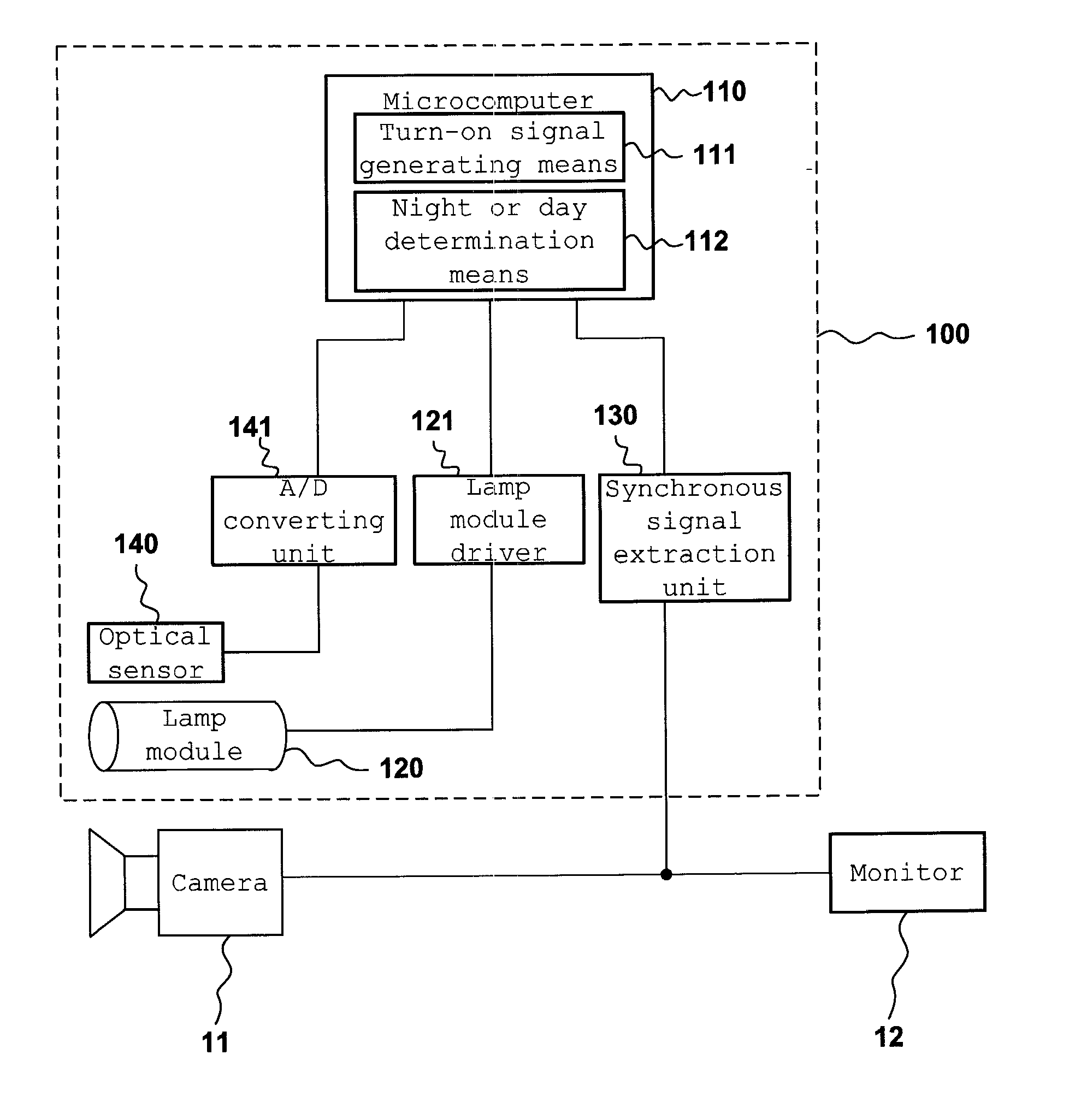
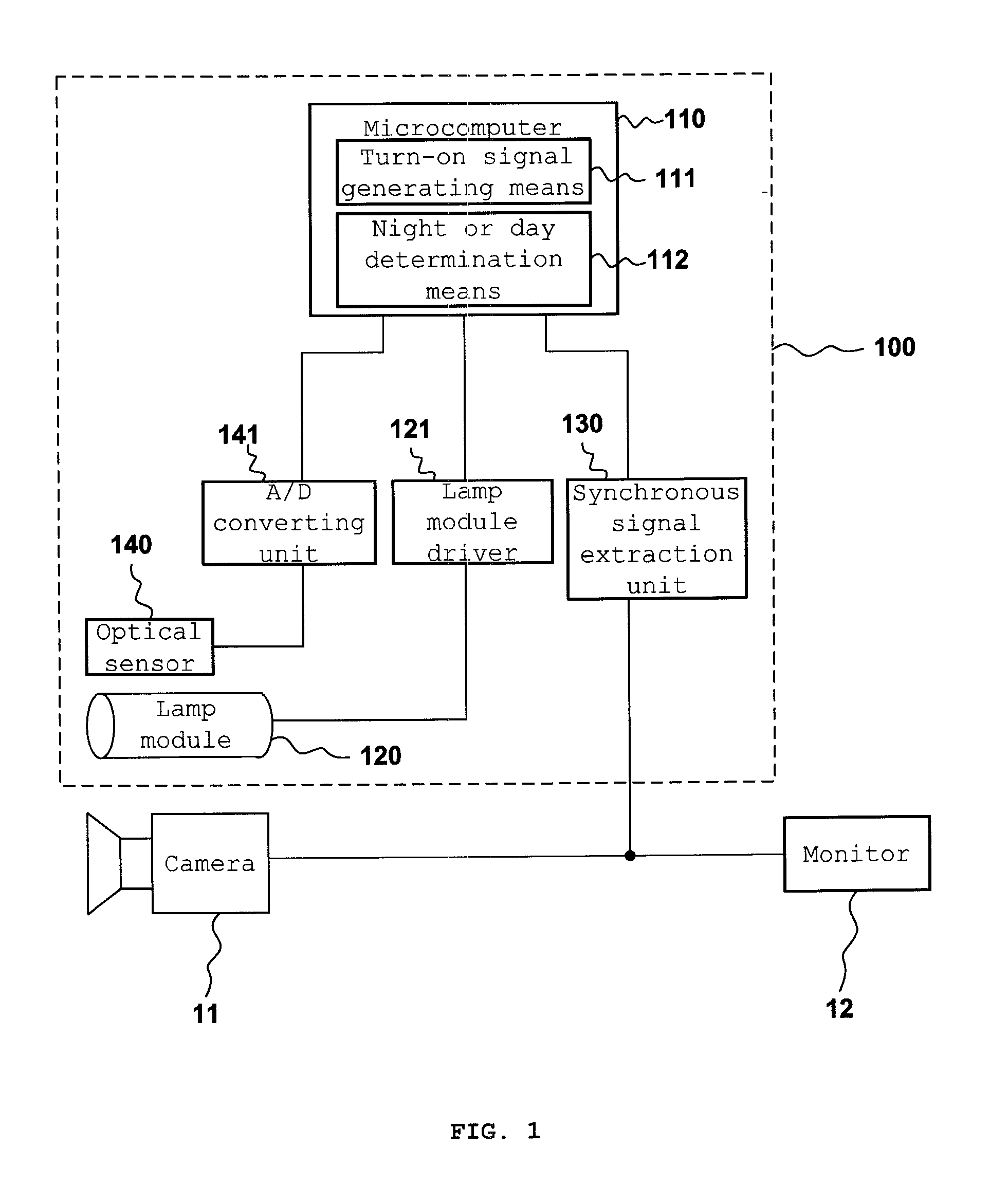
[0035]FIG. 1 is the block diagram of the lighting apparatus (100) for a closed-circuit television according to the exemplary embodiment of the present invention

[0036]FIG. 2 is a drawing showing the video synchronous signal and turn-on signal in the lighting apparatus (100) for a closed-circuit television according to the exemplary embodiment of the present invention;

[0037]The invention is a lighting apparatus for the camera (11) of a closed-circuit television system (10) and it turns on and off in connection with the camera.

[0038]Since the said closed-...


PUM


Abstract

A lighting apparatus and a lighting control method for a closed circuit television camera, which turn on LEDs in accordance with the exposure time of an imaging element in the closed-circuit television camera, and a lighting control system interlocked with the closed circuit television camera, which turns on a plurality of lights in connection with a closed-circuit television system. The lighting apparatus has a lamp module, a lamp module driver, a synchronous signal extraction unit, and a microcomputer which generates a turn-on signal in which pulses corresponding to the shutter exposure time of the imaging element of the camera are repeated using a shutter delay time as a gap, and which drives the lamp module driver in accordance with the generated turn-on signal to turn on the lamp module in the pulse period corresponding to the shutter exposure time.

Description

TECHNICAL FIELD[0001]The present invention relates to a lighting apparatus and to a lighting control method for a closed-circuit television camera, which turns on lights in accordance with the exposure time of an imaging element in the closed-circuit television camera, and to a lighting control system interlocked with the closed-circuit television camera, which turns on a plurality of lights in connection with a closed circuit television system.BACKGROUND ART[0002]Generally for the purposes of monitoring or security, the closed-circuit television (CCTV) system is configured to transmit images of the surveillance area captured by the camera to the Digital Video Recorder (DVR) through transmission lines of a predetermined length, to record transmitted images and / or to output transmitted images on the monitor. The system is applied to various systems, such as the illegal parking enforcement system, parking management system, road traffic monitoring system, water level of a river monito...

Claims


Application Information

Patent Timeline
Patent Type & Authority Applications(United States)
IPC IPC(8): H04N7/18H04N23/90
CPCH04N5/2354H04N7/18H04N5/247H04N23/74H04N23/90
Inventor JEON, DUG GOAN
Owner AMMON TECK
Learn More