Screen unit

a technology for screens and units, applied in the field of screens, can solve the problems of affecting the projection effect, and affecting the image quality, and achieve the effects of easy assembly or storage, low cost, and easy application of tension

Active Publication Date: 2011-09-15
SEIKO EPSON CORP
View PDF8 Cites 4 Cited by
  • Summary
  • Abstract
  • Description
  • Claims
  • Application Information

AI Technical Summary

Benefits of technology

[0008]An advantage of some aspects of the invention is to provide a screen which can be easily assembled while securing sufficient flatness of the surface of the screen, and can be constructed with simple structure and produced at low cost.

Problems solved by technology

Moreover, a person who goes across the front of the projector and thus becomes an obstacle for projection of an image in case of the related-art projector does not pass through the front of the close projection type projector.
According to the close projection type projector, however, the projected image is largely distorted when the surface of the screen has low flatness and has a wavy shape or other non-flat shapes.
According to the close projection type projector, however, the large incident angle of the projection image produces distortion on the projection image when the screen has low flatness, which considerably deteriorates the image quality.
When the close projection type projector projects an image on a screen having low flatness as the screens disclosed in these references, the image quality considerably deteriorates.
However, this screen unit has a complicated structure and is difficult to assemble by a manufacturer or a user.
Furthermore, according to the screen unit disclosed in this reference, expanding and contracting mechanisms using springs are included in supporters, which lowers the rigidity of the supporters.
In this case, stresses are difficult to be uniformly given to the entire surface of the screen base material, and thus the flatness of the screen lowers.
In this case, uniform stresses are applied to the entire surface of the screen, which increases the flatness of the screen.
Thus, easiness of assembly or storage increases.

Method used


Image

  • Screen unit
  • Screen unit
  • Screen unit

Examples


first embodiment

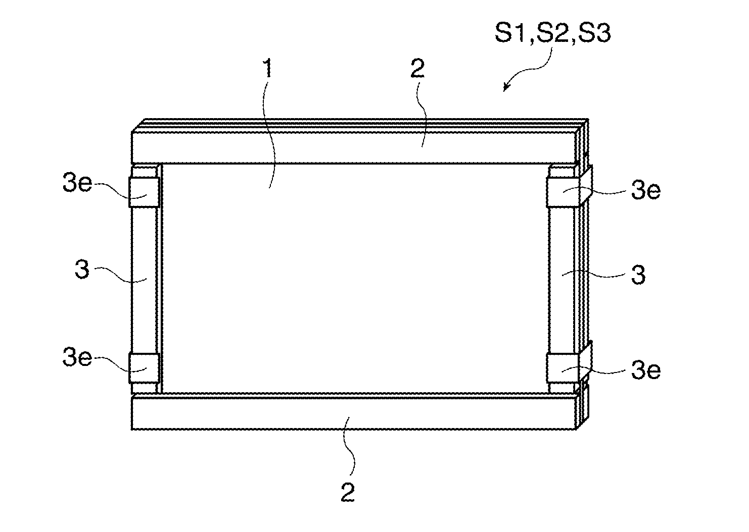
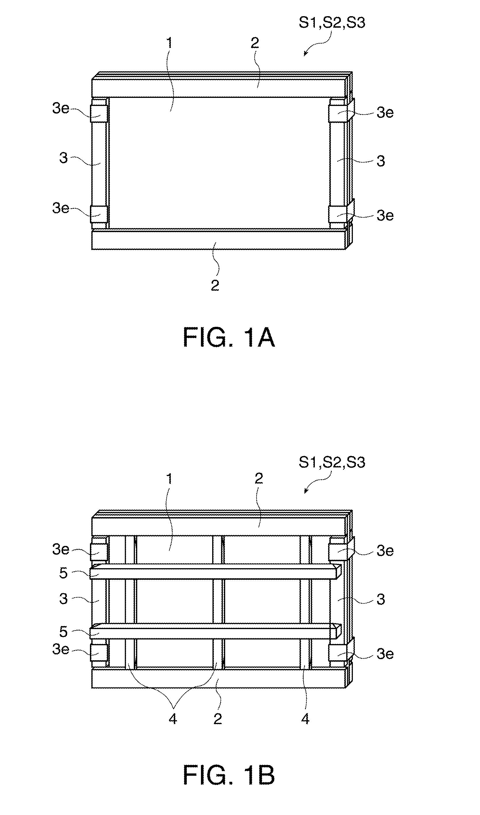
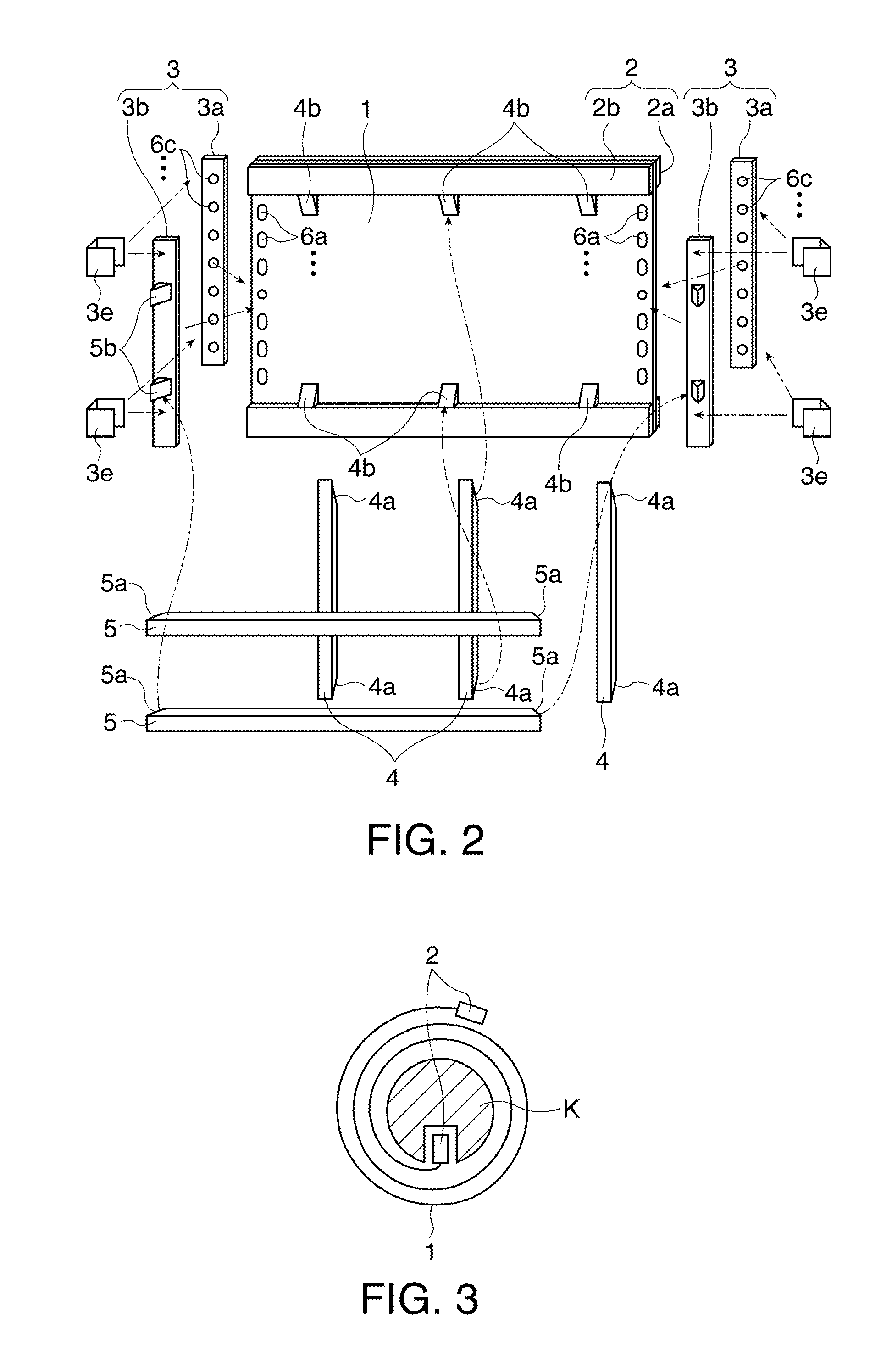
[0032]FIGS. 1A and 1B schematically illustrate the structure of a screen unit S1. FIG. 1A is a perspective view of a surface (front side) of the screen unit S1 on which an image is projected from a projector, and FIG. 1B is a perspective view of the back surface of the screen unit S1. FIG. 2 is a perspective view illustrating a disassembled condition of the screen unit S1. FIG. 3 is a side view showing a stored condition of the screen unit S1.

[0033]FIGS. 1A and 1B illustrate the condition of the screen unit S1 during use according to a first embodiment of the invention. The screen unit S1 includes a rectangular screen 1, first supporting units 2 fixed to a pair of the upper and lower sides of the four sides of the screen 1, second supporting units 3 fixed to a pair of the left and right sides via second bar-shaped members 6b (FIG. 4) as fixing assist members, first tensioning units 4 for applying tension in the direction of separating the first supporting units 2, 2 away from each o...

second embodiment

[0043]A screen unit according to a second embodiment is now explained. A screen unit S2 in the second embodiment is a modification of the screen unit S1 in the first embodiment, and the parts not particularly touched upon herein are similar to the corresponding parts in the first embodiment.

[0044]FIGS. 1A and 1B schematically illustrate the structure of the screen unit S2. FIG. 6 is a perspective view illustrating a disassembled condition of the screen unit S2. FIG. 7 is a side view illustrating a stored condition of the screen unit S2.

[0045]As illustrated in FIG. 6, a plurality of first slip stoppers 7a as fixing assist members are provided on the pair of the left and right sides of the screen 1. The plural first slip stoppers 7a are fixed by an adhesive at intervals of approximately 100 mm along the left and right sides of the screen 1. While only the first slip stoppers 7a on the back side of the screen 1 are shown in the figure, the first slip stoppers 7a are provided on the fro...

third embodiment

[0049]A screen unit according to a third embodiment is now explained. A screen unit S3 in the third embodiment is a modification of the screen unit S1 in the first embodiment, and the parts not particularly touched upon herein are similar to the corresponding parts in the first embodiment.

[0050]FIGS. 1A and 1B schematically illustrate the structure of the screen unit S3. FIG. 9 shows the disassembled screen unit S3.

[0051]As illustrated in FIG. 9, a plurality of first holes 8a are formed on each of the pair of the upper and lower sides of the screen 1. The plural first holes 8a are disposed at intervals of approximately 100 mm along the upper and lower sides of the screen 1, and have opening shapes elongated in the direction of separating the second supporting units 3, 3 away from each other. The plural second holes 8a are not required to have uniform shapes. For example, as illustrated in FIG. 10, a first hole 8a1 located at the intermediate position in the left-right direction of t...


PUM


Abstract

A screen unit includes: a rectangular screen; fixing assist members provided on the screen along two opposed sides of the screen; first supporting units fixed to two sides of the screen different from the two opposed sides along which the fixing assist members are provided; second supporting units fixed to the screen via the fixing assist members; a first tensioning unit which applies tension in the direction of separating the first supporting units away from each other; and a second tensioning unit which applies tension in the direction of separating the second supporting units away from each other.

Description

BACKGROUND[0001]1. Technical Field[0002]The present invention relates to a screen on which an expanded display image produced by a projector is projected, and more particularly to a screen unit which is easy to assemble and has high flatness sufficient for displaying an image projected by a projector without distortion.[0003]2. Related Art[0004]Recently, a close projection type (short focus type) projector which projects an image from a position close to a screen has been put on the market, and the chance of projecting an expanded image on a screen by using this type of projector has been increasing. This close projection type projector which can be placed at a position close to a screen unlike a related-art projector which projects an image from a position away from the screen and thus occupies a wide area on the desk, for example. Moreover, a person who goes across the front of the projector and thus becomes an obstacle for projection of an image in case of the related-art project...

Claims


Application Information

Patent Timeline
Patent Type & Authority Applications(United States)
IPC IPC(8): G03B21/56
CPCG03B21/58
Inventor KATSUMA, RYOJI
Owner SEIKO EPSON CORP
Why Eureka
Try Eureka