Charging Handle for Automatic Rife

Active Publication Date: 2011-09-22
MAGPUL INDUSTRIES
View PDF4 Cites 39 Cited by
  • Summary
  • Abstract
  • Description
  • Claims
  • Application Information

AI Technical Summary

Benefits of technology

[0006]In view of the foregoing disadvantages inherent in the known charging handles, this invention provides an improved charging handle providing both mechanical advantage and gas diversion structures. As such, the present invent

Problems solved by technology

However, certain malfunctions require the user to retract the bolt carrier group with additional force beyond what is necessary for normal operation.
Unfortunately, there are neither any features integral to the M16 system nor are there any aftermarket solutions that allow for additional mechanical advantage to be applied in such circumstances.
This technique requires physical dexterity and greatly reduces the tactical awareness of the user.
Additionally, the use of sound suppression devices was apparently not heavily considered during the development of the M16 system.
These devices increase the duration of the pressure spike of combustion gasses and often times force excess gas around the charging handle and directly into the face of the user.
However, this design does not

Method used


Image

  • Charging Handle for Automatic Rife
  • Charging Handle for Automatic Rife
  • Charging Handle for Automatic Rife

Examples


Embodiment Construction

[0015]With reference now to the drawings, the preferred embodiment of the enhanced charging handle is herein described. It should be noted that the articles “a”, “an” and “the”, as used in this specification, include plural referents unless the content clearly dictates otherwise.

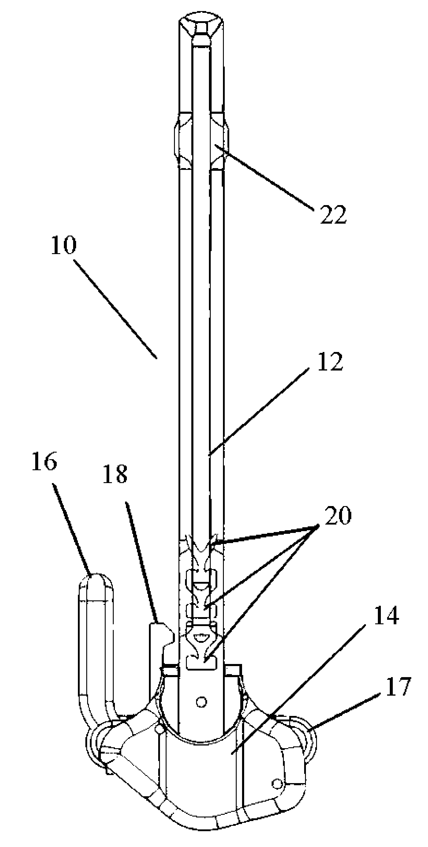
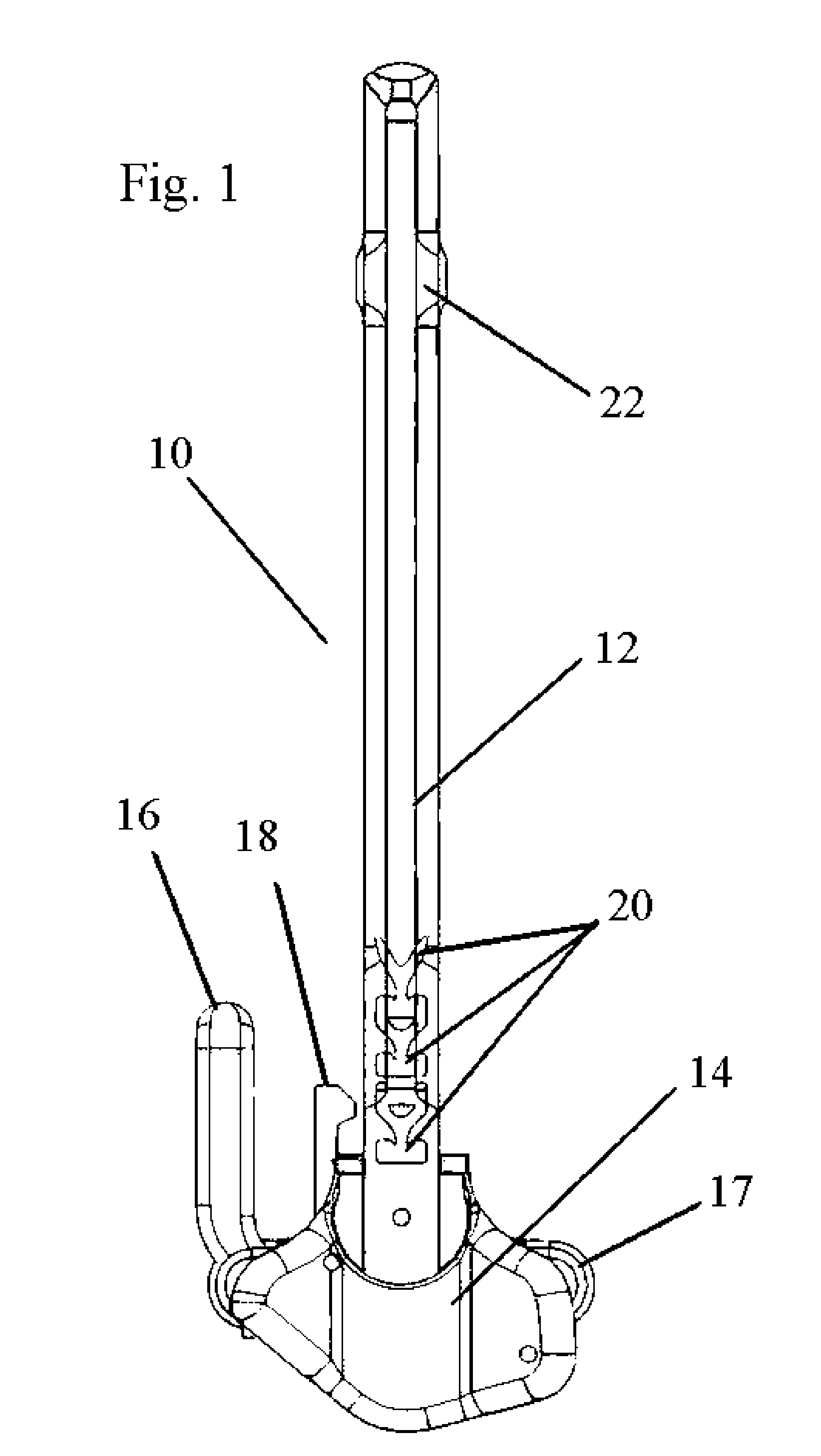
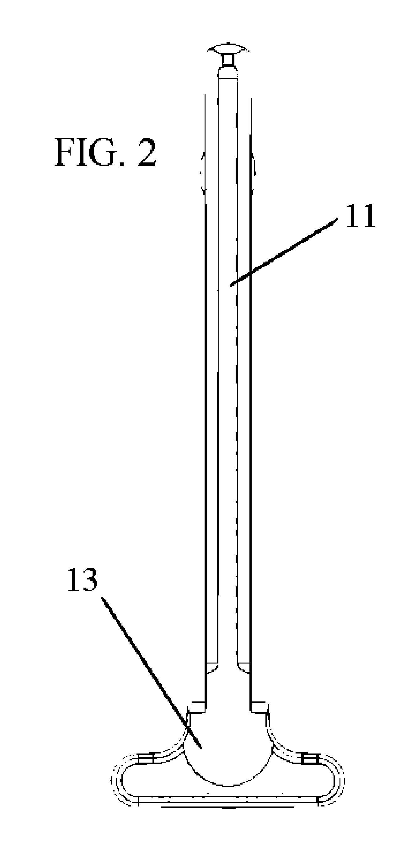
[0016]Referring to FIGS. 1 and 2 the charging handle 10 is initially comprised of a shaft 12 with a connection means (not shown) at one end and a backstop 14 at the other. The connection means is the interface with the bolt carrier group within the rifle, while the backstop 14 is the portion viewable outside the rifle. Shaft 12 is ideally hemispherically hollowed on the underside, with gas diversion means located underneath housing 22. Turbulence induction grooves 20, 24 (shown in FIG. 4) are proximate backstop 14 and assist in diverting gas generated from firing the rifle. Attached to backstop 14 is lever 17, which is, in turn connected to pivot handle 16 and latch 18.

[0017]As shown In FIGS. 3a-3d, the hand...


PUM


Abstract

The present invention is a charging handle for an automatic, bolt actuated rifle. The handle features a ratcheting retraction assist and blowback diversion structures.

Description

FIELD OF THE INVENTION[0001]The field of the present invention is an automatic rifle and more particularly relates to a charging handle for the same.BACKGROUND OF THE INVENTION[0002]The use of bolt operated automatic and semi-automatic rifles is widespread and in all military and law-enforcement environments. Under normal operating conditions, a user can manually retract the bolt carrier group of such rifles by pulling back on the charging handle in order to load the rifle or to clear stoppages. However, certain malfunctions require the user to retract the bolt carrier group with additional force beyond what is necessary for normal operation. Unfortunately, there are neither any features integral to the M16 system nor are there any aftermarket solutions that allow for additional mechanical advantage to be applied in such circumstances. Standard techniques for clearing such a malfunction require the user to remove the rifle from the shoulder and strike the butt of the rifle against a...

Claims


Application Information

Patent Timeline
IPC IPC(8): F41A19/47F41A19/00F41A19/06
CPCF41A19/47
Inventor FITZPATRICK, RICHARD M.NAKAYAMA, BRIAN L.NAKAYAMA, ERIC S.
Owner MAGPUL INDUSTRIES
Why Eureka
Try Eureka