
Driving support device, method, and program

Inactive Publication Date: 2011-09-22
AISIN AW CO LTD
View PDF4 Cites 15 Cited by
  • Summary
  • Abstract
  • Description
  • Claims
  • Application Information

AI Technical Summary

Benefits of technology

[0016]In addition, as an example of a configuration to indirectly inform the charging time period, a configuration to classify the charging time period into a plurality of stages and indicate the corresponding stage may be applied. For example, it is applicable to provide information on states in which the charging time period is zero, more than zero but less than or equal to a predetermined time period, and more than a predetermined time period, as different stages. According to this configuration, it is possible to inform the driver of the length of the charging time period in a simple and easily-understandable manner.
[0019]Further, the information on the state in which the charging time period is less than or equal to the predetermined time period may be provided together with information indicating the position of the charging facility. This information enables the driver to easily determine the charging facility necessary for traveling without using up the electric power of the battery.
[0021]Any routes can be applied as the route from the position of the vehicle to the registered position. However, a route going through the charging facility that exists in an opposite direction of the registered position with respect to the position of the vehicle may be provided. According to this configuration, it is possible to provide information indicating the charging time period that is required when the vehicle further travels ahead of the position of the vehicle instead of traveling directly from the position of the vehicle to the registered position, thereby increasing options for route selection. In addition, the charging facility that exists in the opposite direction of the registered position with respect to the position of the vehicle may be for example a charging facility that exists in an area where the registered position does not exist of areas given by dividing by a straight line that is perpendicular to a straight line connecting the position of the vehicle and the registered position and passes the position of the vehicle.
[0022]A relative positional relation among the position of the vehicle, the registered position, and the charging facility may be explicitly indicated together with the charging time period. For example, in case of the same charging time period, it may be explicitly indicated to the driver whether the charging facility, with which the registered position can be reached through charging for the charging time period, exists in the same direction as the registered position with respect to the position of the vehicle or in the opposite direction of the registered position with respect to the position of the vehicle. According to this configuration, the driver can easily recognize whether or not the vehicle can travel further ahead of the position of the vehicle and a travel direction in which the vehicle can continue to travel.

Problems solved by technology

Consequently, even when a charging facility where charging may be possible before reaching the registered position such as the home exists, it is not possible to perform the charging at the charging facility unless a driver is aware of the position of the charging facility.
Thus, it is not possible in practice to perform the charging at a place other than the home even when the recommendation to charge the battery is given.

Method used


Image

  • Driving support device, method, and program
  • Driving support device, method, and program
  • Driving support device, method, and program

Examples


Embodiment Construction

[0029]The aspects of the present invention are described in further detail below with reference to embodiments in the following order.

[0030](1) Structure of Navigation Device:

[0031](2) Driving Support Processing:

[0032](3) Other embodiments:

[0033](1) Structure of Navigation Device:

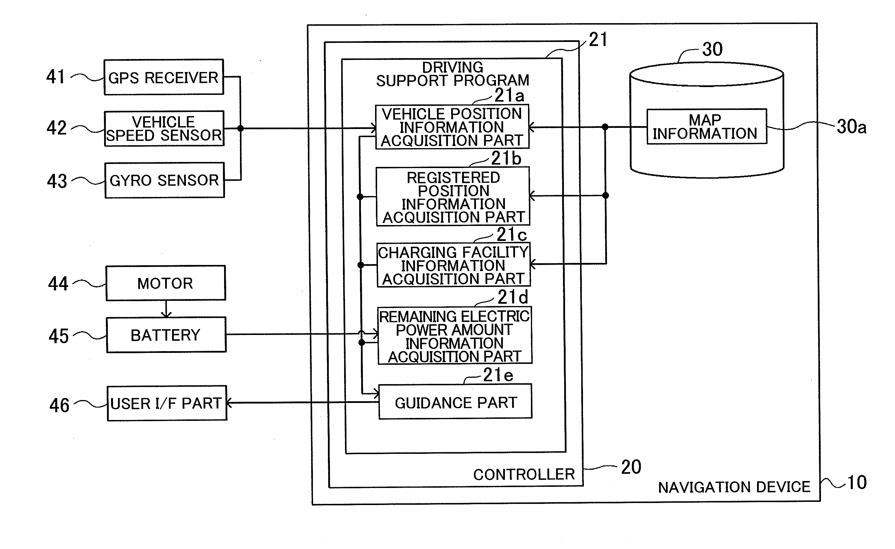
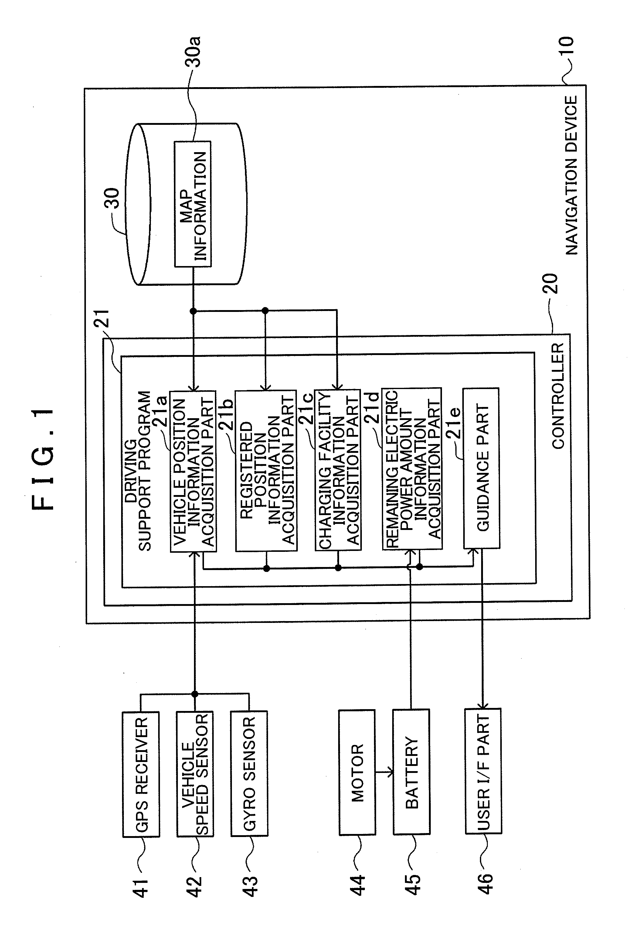
[0034]FIG. 1 is a block diagram showing a structure of a navigation device 10 including a driving support device according to an exemplary embodiment of the present invention. The navigation device 10 includes a controller 20 and a storage medium 30. The controller 20 includes a CPU, a RAM, a ROM, and the like. Programs stored in the storage medium 30 and the ROM can be executed in the controller 20. In the present embodiment, a driving support program 21 can be executed as such program. The driving support program 21 includes a function that provides information indicating a charging time period at a charging facility that is required for traveling a route from a current position to a registered position. ...


PUM


Abstract

Provided is a driving support device and method that includes a charging facility information acquisition unit that acquires information indicating a position and a charging capacity of a charging facility that exists within a predetermined distance from a position of a vehicle and a guidance unit that provides information indicating a charging time period at the charging facility based on the position of the vehicle, a registered position, the position and the charging capacity of the charging facility, and a remaining electric power amount of a battery in the vehicle and information indicating a charging time period at the charging facility that is required for traveling a route from the position of the vehicle to the registered position by electric power of the battery.

Description

INCORPORATION BY REFERENCE[0001]This application claims priority from Japanese Patent Application No. 2010-064127 filed on Mar. 19, 2010, including the specification, drawings and abstract thereof, the disclosure of which is incorporated herein by reference in its entirety.BACKGROUND OF THE INVENTION[0002]1. Field of the Invention[0003]Aspects of the present invention relate to a driving support device, a method, and a program in a vehicle that travels using electric power from a battery.[0004]2. Description of the Related Art[0005]In the related are, a technology that prevents using up the electric power of the battery in the vehicle traveling by the electric power of the battery, is known. For example, Japanese Patent Application; Publication No. JP-A-2009-89756 discloses a technology that recommends charging a battery if the remaining electric power of the battery drops below a first percentage of the electric power amount required to return home, and starts navigation processing...

Claims


Application Information

Patent Timeline
IPC IPC(8): H02J7/00
CPCB60L11/1838Y02T90/121B60L11/1861B60L15/2045Y02T10/7005Y02T10/7044Y02T10/705Y02T10/7283Y02T90/128Y02T90/14Y02T90/163G01C21/3469Y02T90/161Y04S10/126Y02E60/721B60L11/1844Y02T10/7072Y02T10/72B60L53/63Y02E60/00Y02T10/64Y02T10/70Y02T90/16Y02T90/12
Inventor NIWA, TOSHIAKI
Owner AISIN AW CO LTD
Learn More