Methods for detecting a hidden peak in wire fault location applications - improving the distance range resolution

a fault location and hidden peak technology, applied in the field of methods and apparatus for detecting hidden peak in wire fault location technologies, can solve the problems of affecting the timing of the return of the reflection relative to the original pulse, and affecting the accuracy of the detection

Inactive Publication Date: 2011-09-22
HONEYWELL INT INC
View PDF11 Cites 31 Cited by
  • Summary
  • Abstract
  • Description
  • Claims
  • Application Information

AI Technical Summary

Problems solved by technology

Aircraft wiring problems have recently been identified as the likely cause of several tragic mishaps and hundreds of thousands of lost mission hours.
Aircraft wiring is often routed behind panels or wrapped in special protective jackets and is not accessible, even during heavy maintenance when most of the panels are removed.
However, if under certain circumstances, the reflected signal overlaps with the original test signal, the determination of the timing of the return of the reflection relative to the original pulse becomes very difficult.
If the hidden / overlapped peak issue is not properly resolved, a legitimate wire fault could be overlooked.

Method used


Image

  • Methods for detecting a hidden peak in wire fault location applications - improving the distance range resolution
  • Methods for detecting a hidden peak in wire fault location applications - improving the distance range resolution
  • Methods for detecting a hidden peak in wire fault location applications - improving the distance range resolution

Examples


Embodiment Construction

[0028]The following detailed description is of the best currently contemplated modes of carrying out exemplary embodiments of the invention. The description is not to be taken in a limiting sense, but is made merely for the purpose of illustrating the general principles of the invention, since the scope of the invention is best defined by the appended claims.

[0029]Various inventive features are described below that can each be used independently of one another or in combination with other features.

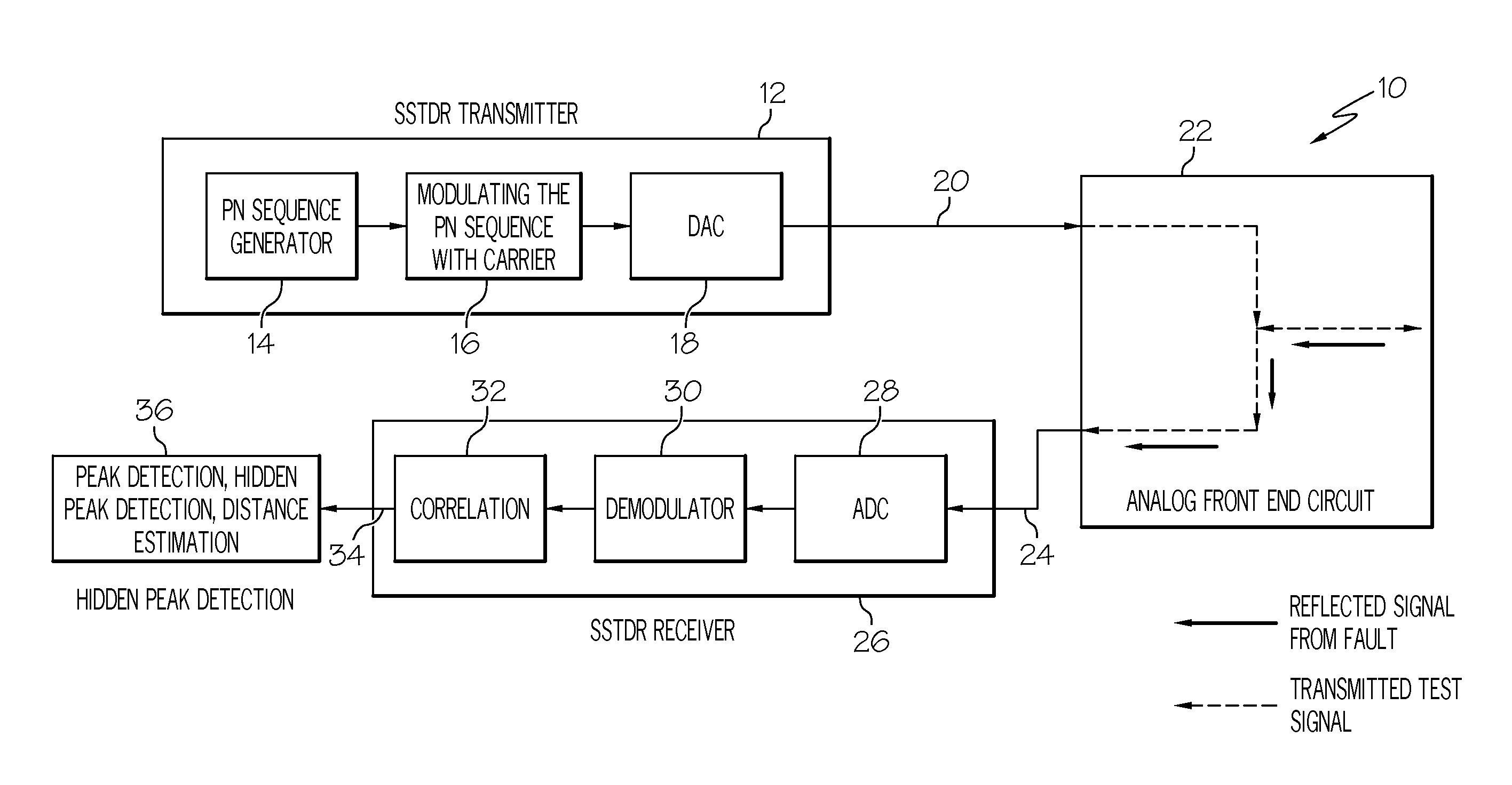
[0030]Broadly, embodiments of the present invention provide methods for detecting hidden / overlapped peaks that may occur when using SSTDR technology to determine ware faults. These hidden / overlapped peaks may cause false negative determinations (no fault) when testing a wire for faults. In one method according to an exemplary embodiment of the present invention, the symmetrical property of the SSTDR wave envelope is used to resolve hidden / overlapped peaks. In another method according to an...


PUM


Abstract

Hidden or overlapped peaks may occur when using SSTDR technology to determine ware faults. These hidden / overlapped peaks may cause false negative determinations (no fault) when testing a wire for faults. In one method of the present invention, the symmetrical property of the SSTDR wave envelope is used to resolve hidden / overlapped peaks. In another method of the present invention, the calibrated normalized loop back SSTDR wave envelope may be used to resolve hidden / overlapped peaks.

Description

BACKGROUND OF THE INVENTION[0001]The present invention relates to methods and apparatus for detecting hidden peaks in wire fault location technologies and, more particularly, to methods for resolving overlapping and / or hidden peaks detected through spread spectrum time domain reflectometry (SSTDR).[0002]Aircraft wiring problems have recently been identified as the likely cause of several tragic mishaps and hundreds of thousands of lost mission hours. Aircraft wiring is often routed behind panels or wrapped in special protective jackets and is not accessible, even during heavy maintenance when most of the panels are removed. A wire testing method that could test the wires continually, including while the plane is in flight would, therefore, have a tremendous advantage over conventional static test methods.[0003]Various technologies in detecting and pin-pointing the wiring problems have been proposed and developed to address safety concerns, among which, spread spectrum time domain re...

Claims


Application Information

Patent Timeline
Patent Type & Authority Applications(United States)
IPC IPC(8): G01R31/11
CPCG01R31/11G01R31/008
Inventor AHAMED, SHAIK SHAFIDANGETI, SRINIVASA RAOPESALA, NARASIMHA RAOPEDDAIAH, THAPPETAVEDICHERLA, SREENIVASULU REDDYSUBRAMANYAM, VEDAGIRIBABULIU, ZHENNING
Owner HONEYWELL INT INC
Why Eureka
Try Eureka