Insulation test method for large-scale photovoltaic systems
Inactive Publication Date: 2011-09-22
ADENSIS
View PDF10 Cites 26 Cited by
Summary
Abstract
Description
Claims
Application Information
AI Technical Summary
This helps you quickly interpret patents by identifying the three key elements:
Problems solved by technology
Method used
Benefits of technology
Benefits of technology
[0012]Thus, this method does not take the obvious route of further developing the tester, but instead pursues the course of changing the photovoltaic system, or rather making it more easily subdivided, in such a way that standard testers can be used. This can involve higher device costs, but at an acceptable level.
[0017]The current sensors can be provided at the feed lines leading to individual arrays of the photovoltaic system proceeding from a bus bar. This is especially advantageous when additional switching means are provided that connect the relevant connecting lines leading to the individual arrays to the bus bar or isolate said connecting lines therefrom. The bus bar is connected to the input of the inverter here.
Problems solved by technology
This can involve higher device costs, but at an acceptable level.
Method used
Image
Click on the blue label to locate the original text in one second.
Reading with bidirectional positioning of images and text.
Examples
first embodiment
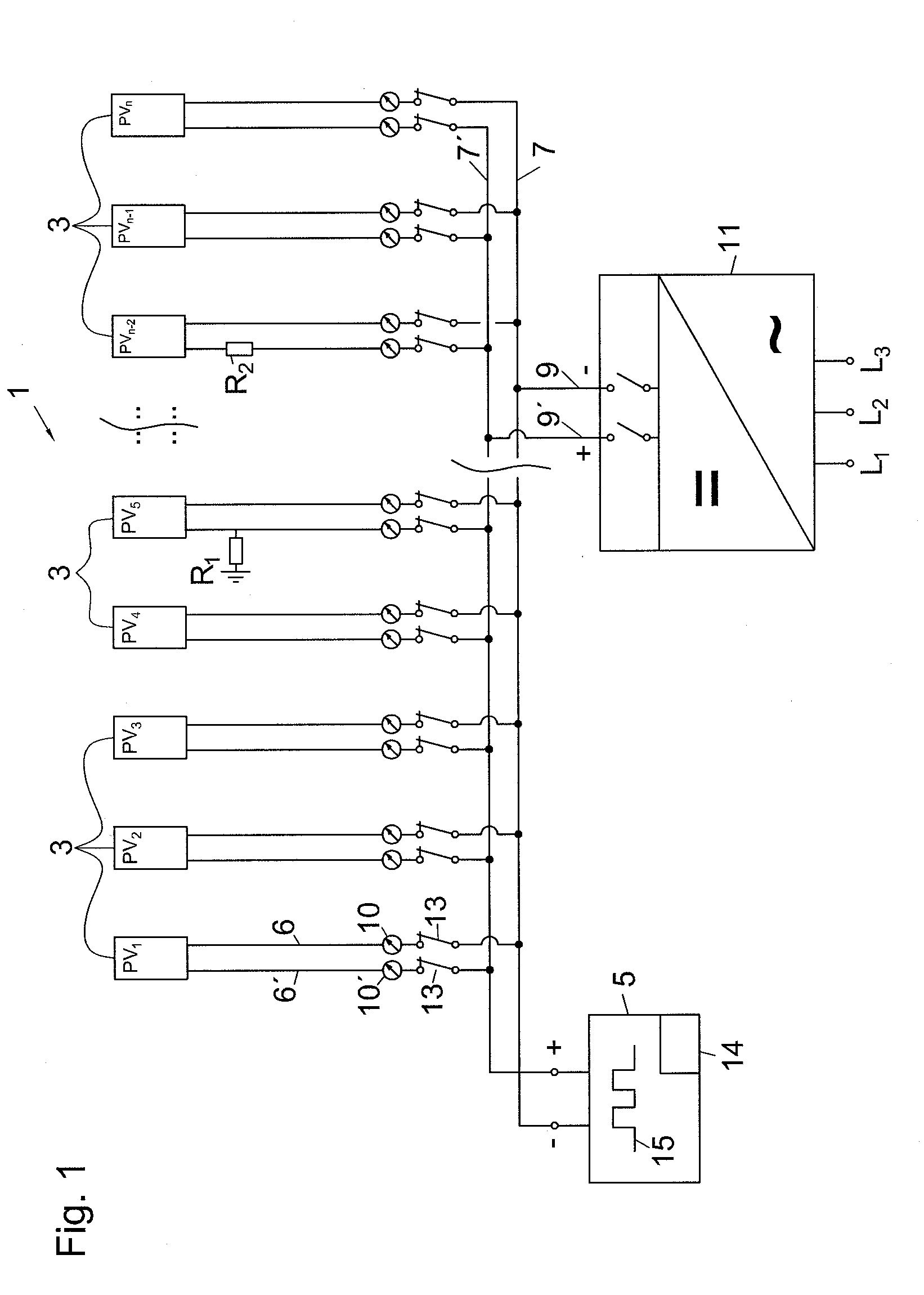
[0026]This is permitted by the instant first embodiment in that the insulation monitor 5 transmits its test pulse 15 directly to the bus bars 7,7′ without needing to have actuated the disconnect switches 13. For example, this can be done at night, when no solar-generated voltage is present. With suitably high-resistance insulation of the insulation monitor 5, the test pulse 15 can also be modulated onto the bus bars 7,7′ in the daytime during ongoing operation of the photovoltaic system 1.
[0027]If the feed lines 6,6′ to all subsystems 3, as well as the subsystems 3 themselves, are in a properly insulated state, then the test pulse 15 transmitted on the positive bus bar 7′ would be distributed more or less uniformly over the subsystems 3 in accordance with the particular line lengths present, and the ammeters 10′ would indicate approximately the same value. The ammeters 10 measuring the return current likewise indicate the same current value except for the damping losses that are to ...
second embodiment
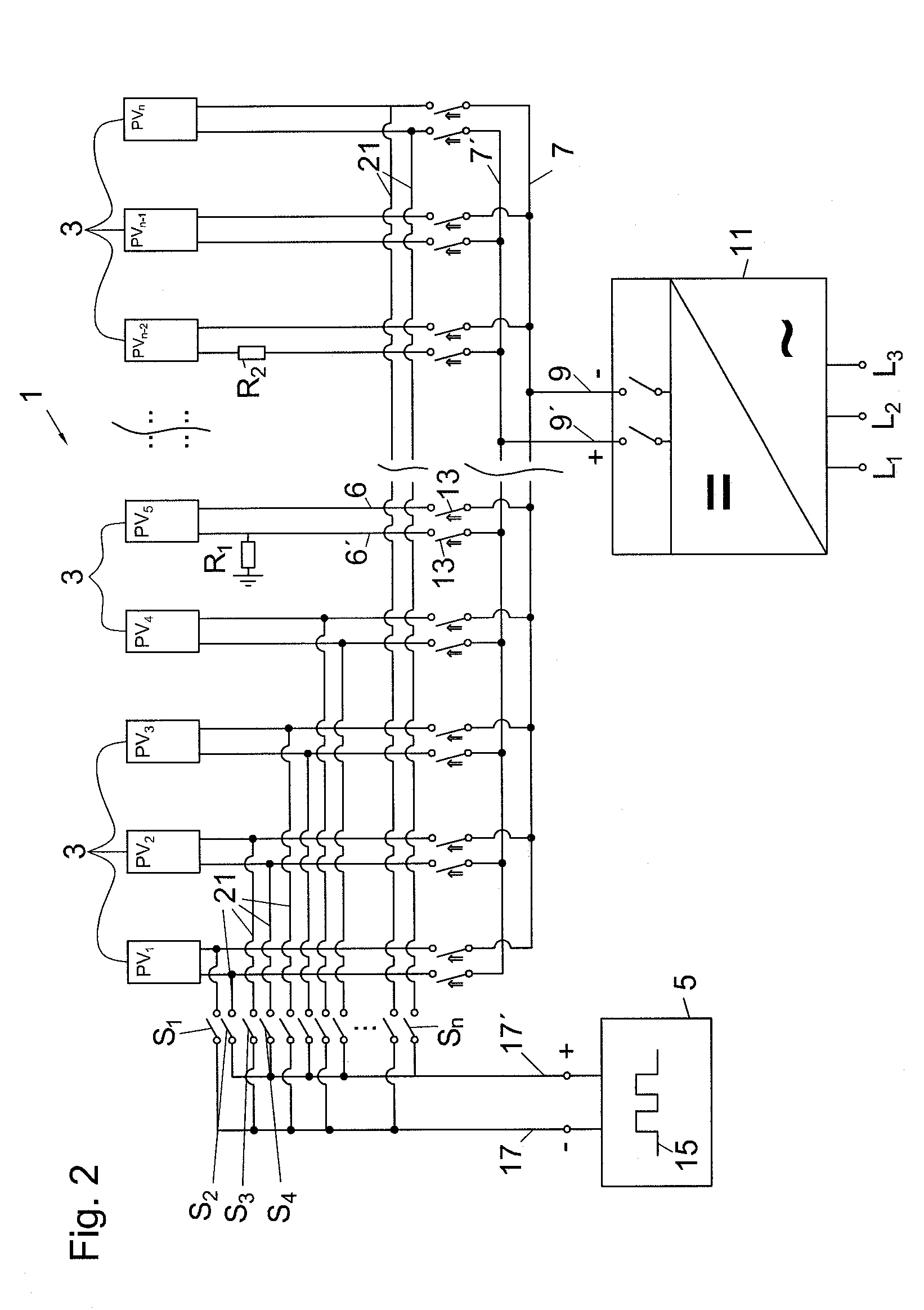
[0030]In the invention shown in FIG. 2, the insulation monitor 5 transmits the test pulse 15 on two test pulse bus bars 17,17′, whence it can be switched according to the invention by means of two or more two-pole switches S onto connecting lines 21,21′, also referred to below in connection with FIG. 3 as stub lines 21,21′, each of which terminates in associated feed lines 6,6′.
[0031]If the first subsystem PV1 is to be tested for insulation weaknesses, then all other switches S2 to Sn of the subsystems PV2 to PVn are opened, and only the switch S1, which connects the feed lines 6,6′ of the first subsystem PV1 to the test pulse bus bars 17,17′, is closed. In this way it is made possible, even for the large-scale system 1, to test the insulation with a conventional insulation monitor 5 in the accustomed manner.
[0032]In this way, all subsystems PVn are gradually connected to the insulation monitor 5, by the means that only the relevant switch S that is associated with the subsystem PV ...
PUM
Abstract
In large-scale photovoltaic systems, it is not appropriate to use a conventional insulation monitor, since its test pulse is damped too much by the number and length of the feed lines. According to an embodiment of the invention, a remedy is provided here in that the photovoltaic system is subdivided through circuit design into multiple subsystems that are electrically insulated from one another, and the test pulse is transmitted to the connecting line associated with the applicable subsystem in sequential order. According to a second embodiment, the behavior of the current of the test pulse through the connecting lines is sensed by current sensors and evaluated in an analysis unit.
Description
[0001]This nonprovisional application claims priority under 35 U.S.C. §119(a) to German Patent Application No. DE 10 2010 011 476.6, which was filed in Germany on Mar. 16, 2010, and which is herein incorporated by reference.BACKGROUND OF THE INVENTION[0002]1. Field of the Invention[0003]The invention relates to a method for testing the insulation of a photovoltaic system from ground with the aid of a test pulse transmitted to the connecting lines of the photovoltaic system.[0004]2. Description of the Background Art[0005]A method for protecting a PV system is known from WO95 / 25374. This method reacts once damage has already occurred, in that an attempt is made to limit the effects of the damage on the photovoltaic system by the means that the electromagnetic radiation accompanying the short-circuit arc is detected and the affected system components are isolated from the short-circuit.[0006]Known from the document DE 10 2004 018918 is an insulation fault localization method in the fie...
Claims
Application Information
Patent Timeline
Application Date:The date an application was filed.
Publication Date:The date a patent or application was officially published.
First Publication Date:The earliest publication date of a patent with the same application number.
Issue Date:Publication date of the patent grant document.
PCT Entry Date:The Entry date of PCT National Phase.
Estimated Expiry Date:The statutory expiry date of a patent right according to the Patent Law, and it is the longest term of protection that the patent right can achieve without the termination of the patent right due to other reasons(Term extension factor has been taken into account ).
Invalid Date:Actual expiry date is based on effective date or publication date of legal transaction data of invalid patent.

