Various Configurations Of The Viewing Window Based 3D Display System

a display system and display window technology, applied in the field of displays, can solve the problems of cumbersome approach, dimmer image, and inability to perceive stereo effect or correctly, and achieve the effect of increasing the viewing area

Active Publication Date: 2011-09-22
SEIKO EPSON CORP
View PDF15 Cites 9 Cited by
  • Summary
  • Abstract
  • Description
  • Claims
  • Application Information

AI Technical Summary

Benefits of technology

[0010]It is an object of the present invention to create a retro-reflective display with increased viewing area.

Problems solved by technology

Although this approach is effective, the required headgear (such as head-mounted displays or glasses with specialized lenses for rejecting specific angle views) makes this approach cumbersome.
Parallel-barrier displays use light blocking to produce viewing windows, but this approach results in a dimmer image since only a small amount of light emitted from each pixel passing through the barrier window.
Overlap of viewing areas causes crosstalk causing one eye to see the image intended for the other eye.
When crosstalk is significant, the one cannot perceive the stereo effect or cannot perceive it correctly.
Parallel-barrier displays also use small apertures that can cause diffraction, particularly as the display resolution is increased.
As the display resolution increases, the barrier aperture size is decreased, which causes more severe diffraction effects.
Parallel-barrier displays suffer from dark pixel lines due to each view seeing only one pixel column out of n associated with one barrier window.
Lenticular-based displays offer higher resolution compared with the barrier slits of parallel-barrier-based displays, but they are generally more difficult and costly to make due to the need for high quality lenticular sheets.
Aligning a lenticular sheet with a display also requires significant effort.
Although lenticular-based displays offer benefits over parallel-barrier-based displays, lenticular-based displays also suffer from crosstalk between view windows, dark line problem, limited resolution, and limit number of viewing windows.

Method used


Image

  • Various Configurations Of The Viewing Window Based 3D Display System
  • Various Configurations Of The Viewing Window Based 3D Display System
  • Various Configurations Of The Viewing Window Based 3D Display System

Examples


Embodiment Construction

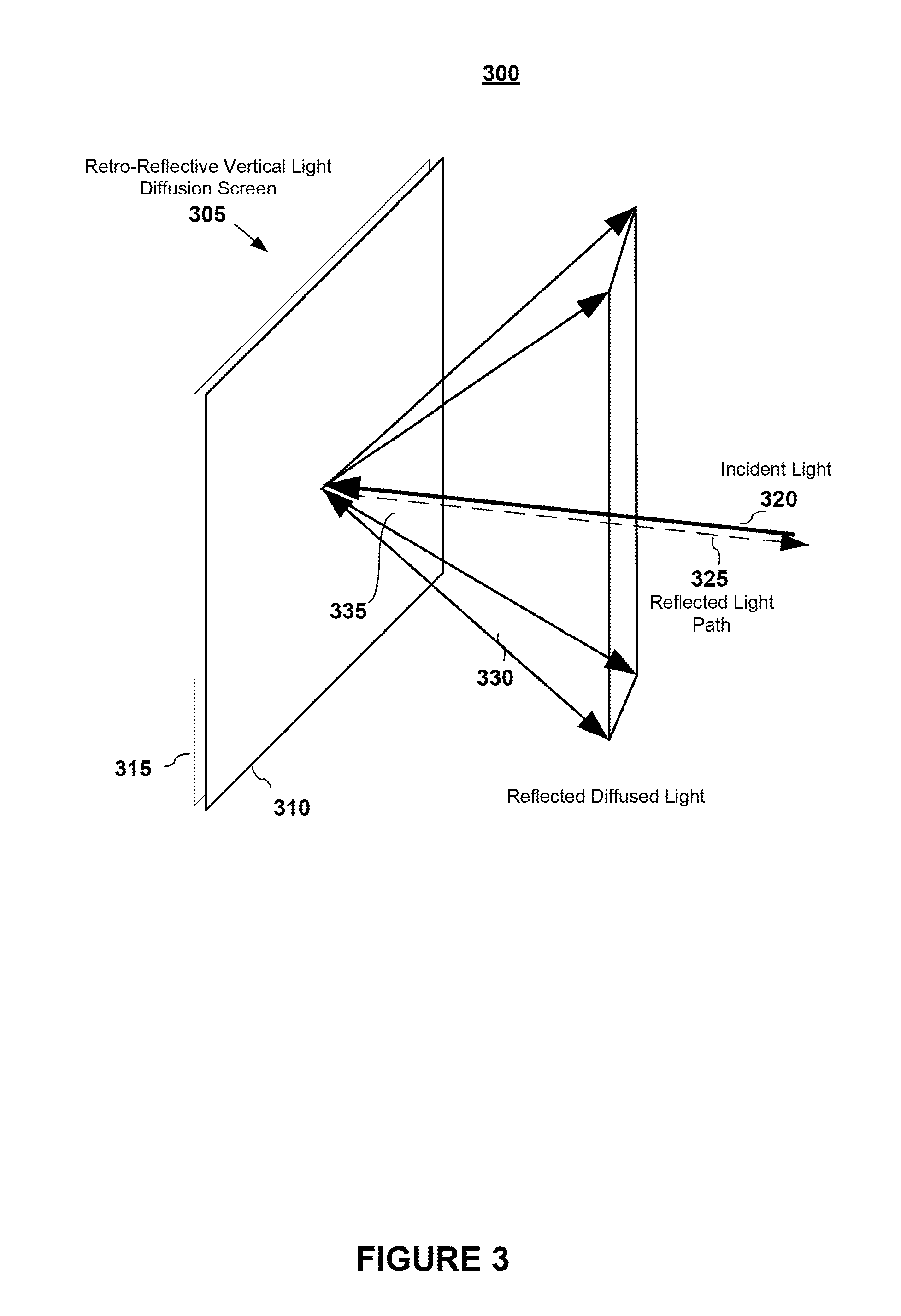
[0039]The presently preferred embodiment makes use of a retro-reflective vertical light diffusion screen. Such a screen is typically comprised of two layers: a first layer of a one-dimensional (1D) light diffusion material (which has a small diffusion angle in one direction and a large diffusion angle in another direction) and a second layer of a retro-reflective material (which reflects light rays back at their respective incident angle).

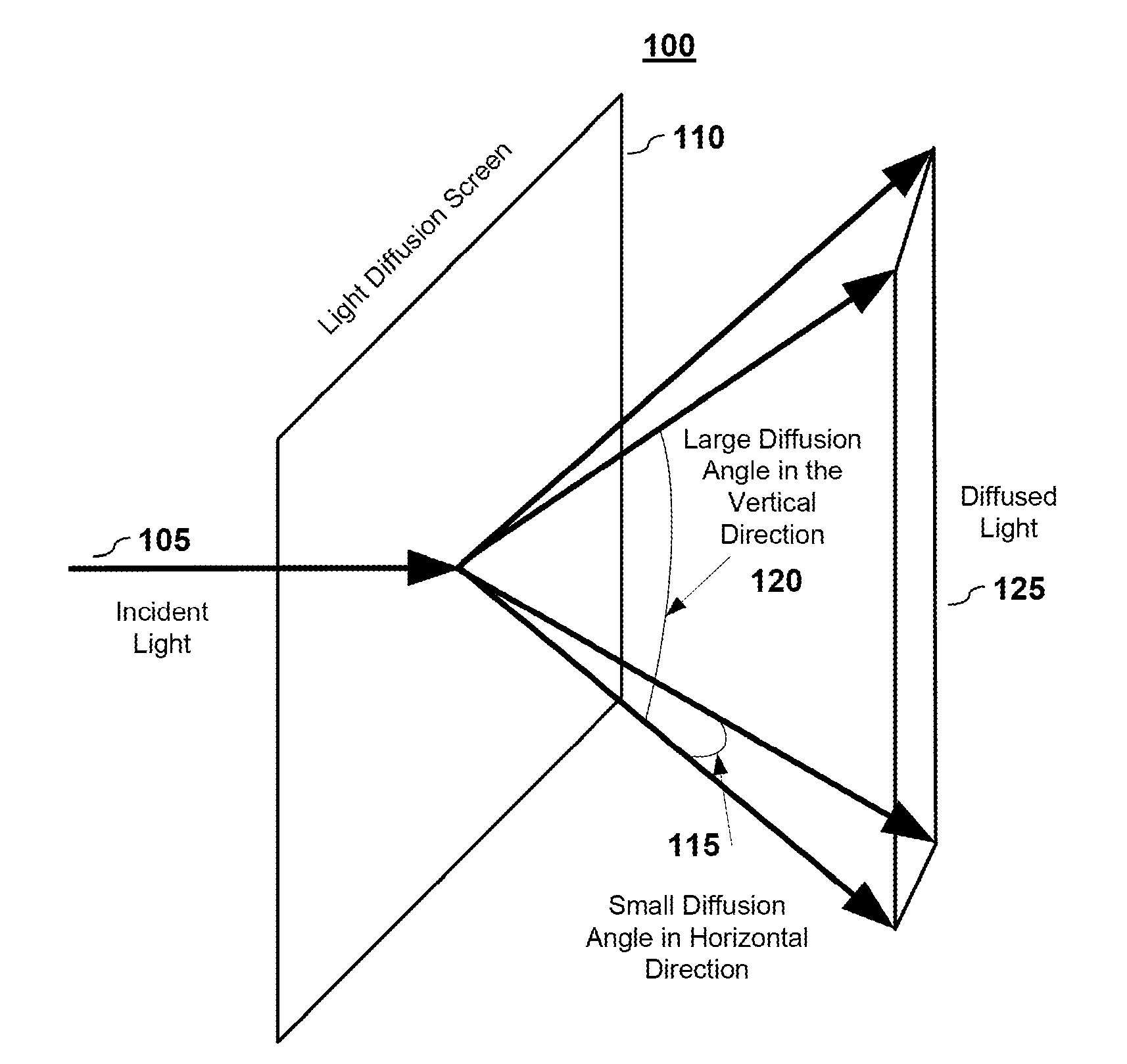
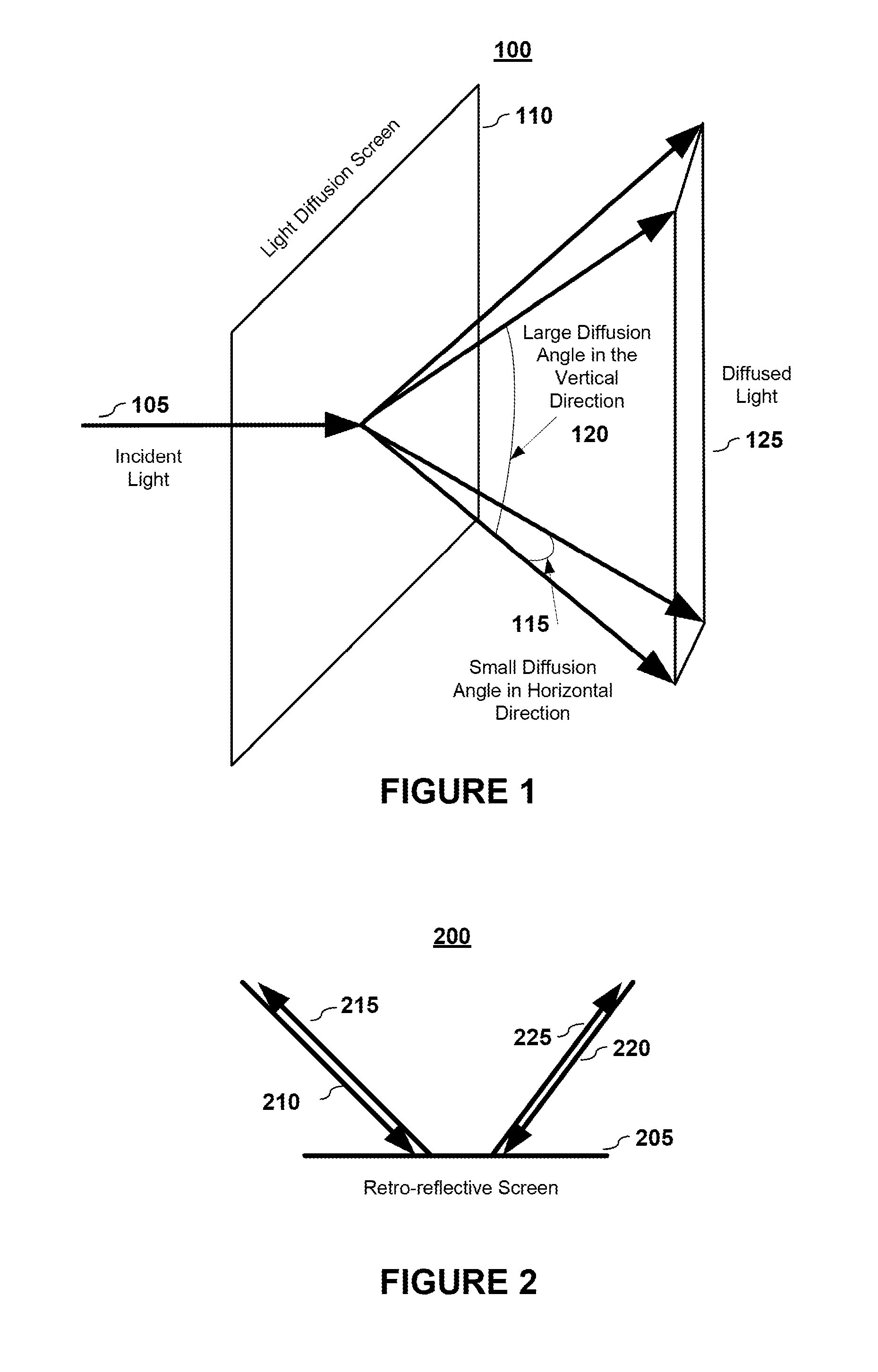
[0040]With reference to FIG. 1, the first layer 100 consists of a light diffusing material 110. An incident light ray 105 that passes through light diffusing material 110 is diffused by a small angle 115 in the horizontal direction and diffused by a large angle 120 is the vertical direction. This creates a diffused light window 125. This type of diffusion screen can be referred to as a vertical light diffusion screen.

[0041]With reference to FIG. 2, the second layer of the retro-reflective vertical light diffusion screen includes a retro-reflective ...


PUM


Abstract

A panoramic 3D image is created by using multiple projectors whose field-of-view is narrower than the screen's width. Each projector provides a different image of a common subject from a different view angle, and the different images are mosaiced onto the screen. An observer may have a limited view of the composite image depending on which projectors are within the observer's field-of-view. A viewing volume is also extended by using space beyond a far limit line dependent upon the observer's inter-pupillary distance, the width of each projector's viewing window, and the distance from the projection baseline to the screen

Description

BACKGROUND[0001]1. Field of Invention[0002]The present invention pertains generally to displays, and relates more particularly to wide-view-area and wide-view-screen autostereoscopic three-dimensional (3D) displays.[0003]2. Description of Related Art[0004]Traditionally, stereoscopic, i.e. 3D, images are created by aid of headgear that control viewing of separate left and right stereoscopic images by the left and right eyes, respectively, of a viewer. Each of the left and right images displays the same scene from slightly shifted viewing angles that closely match the viewing angles of a viewer's eyes. By conveying the separate left and right images to the viewers left and right eyes with viewing angles closely matching each eye's normal viewing angle, an illusion of a 3-Dimensional, i.e. 3D, display is created for the viewer.[0005]Although this approach is effective, the required headgear (such as head-mounted displays or glasses with specialized lenses for rejecting specific angle v...

Claims


Application Information

Patent Timeline
Patent Type & Authority Applications(United States)
IPC IPC(8): H04N7/00H04N13/351H04N13/363
CPCG02B27/2278G02B27/2292H04N13/0459H04N13/0402H04N13/0447H04N13/0242H04N13/302H04N13/243H04N13/363H04N13/351G02B30/52G02B30/56
Inventor GAO, CHUNYUXIAO, JING
Owner SEIKO EPSON CORP
Why Eureka
Try Eureka