
Ophthalmologic imaging apparatus and method for controlling the same

Inactive Publication Date: 2011-09-22
CANON KK
View PDF3 Cites 6 Cited by
  • Summary
  • Abstract
  • Description
  • Claims
  • Application Information

AI Technical Summary

Benefits of technology

[0007]According to an aspect of the present invention, an ophthalmologic imaging apparatus includes: a control unit configured to control, based on a pixel value of the optic papilla in an infrared light image of the fundus of a subject's eye to which in

Problems solved by technology

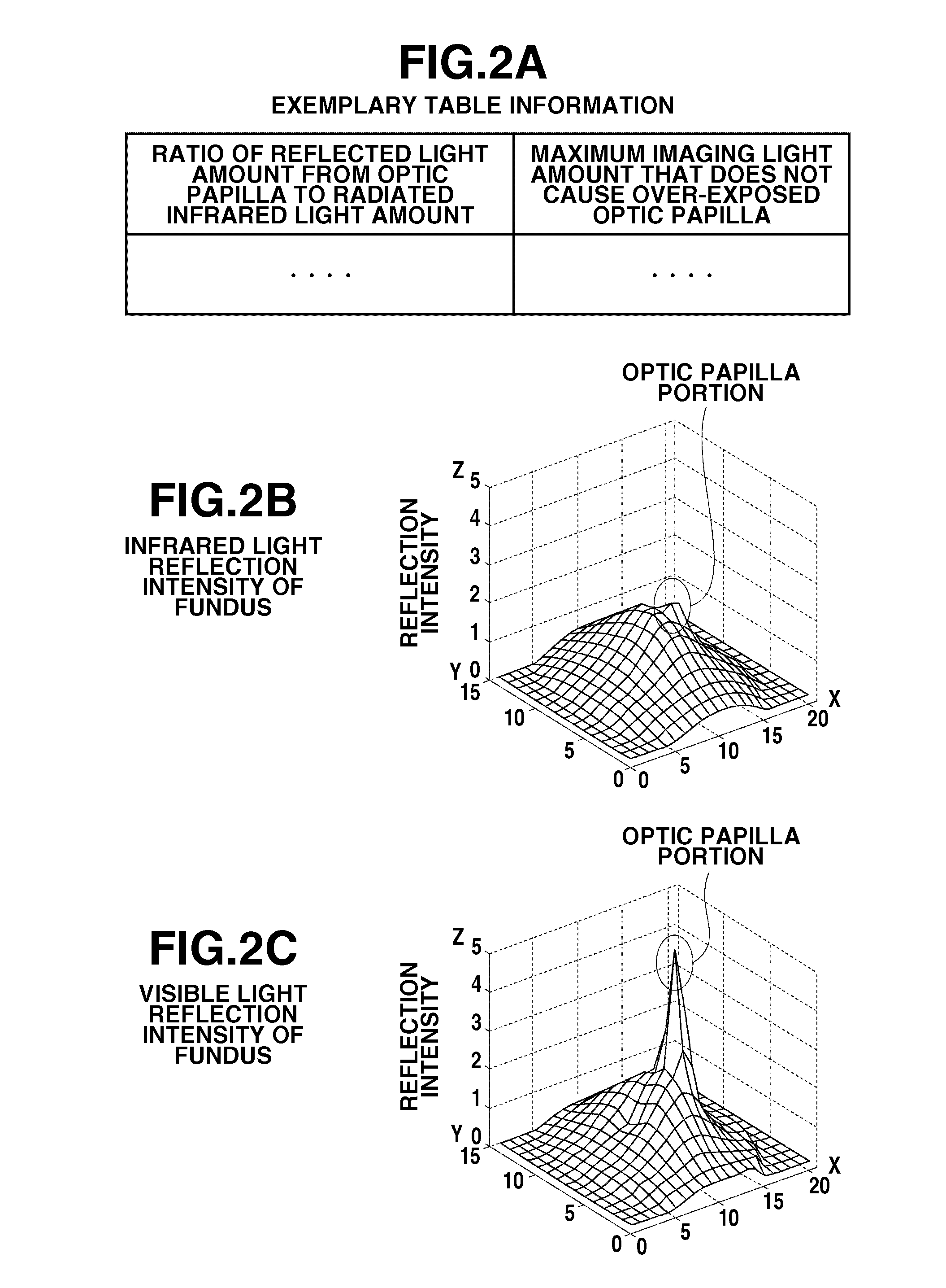
However, this technique has a problem that the optic papilla is over-exposed in the captured fundus image since its large reflectance is not taken into consideration.
This technique has a problem that visible light radiation before imaging causes myosis of the subject's eye.

Method used


Image

  • Ophthalmologic imaging apparatus and method for controlling the same
  • Ophthalmologic imaging apparatus and method for controlling the same
  • Ophthalmologic imaging apparatus and method for controlling the same

Examples


Embodiment Construction

[0021]Various exemplary embodiments, features, and aspects of the invention will be described in detail below with reference to the drawings.

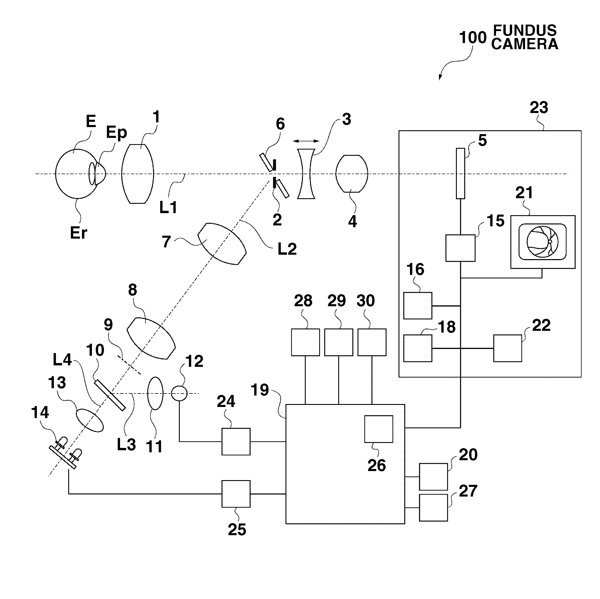
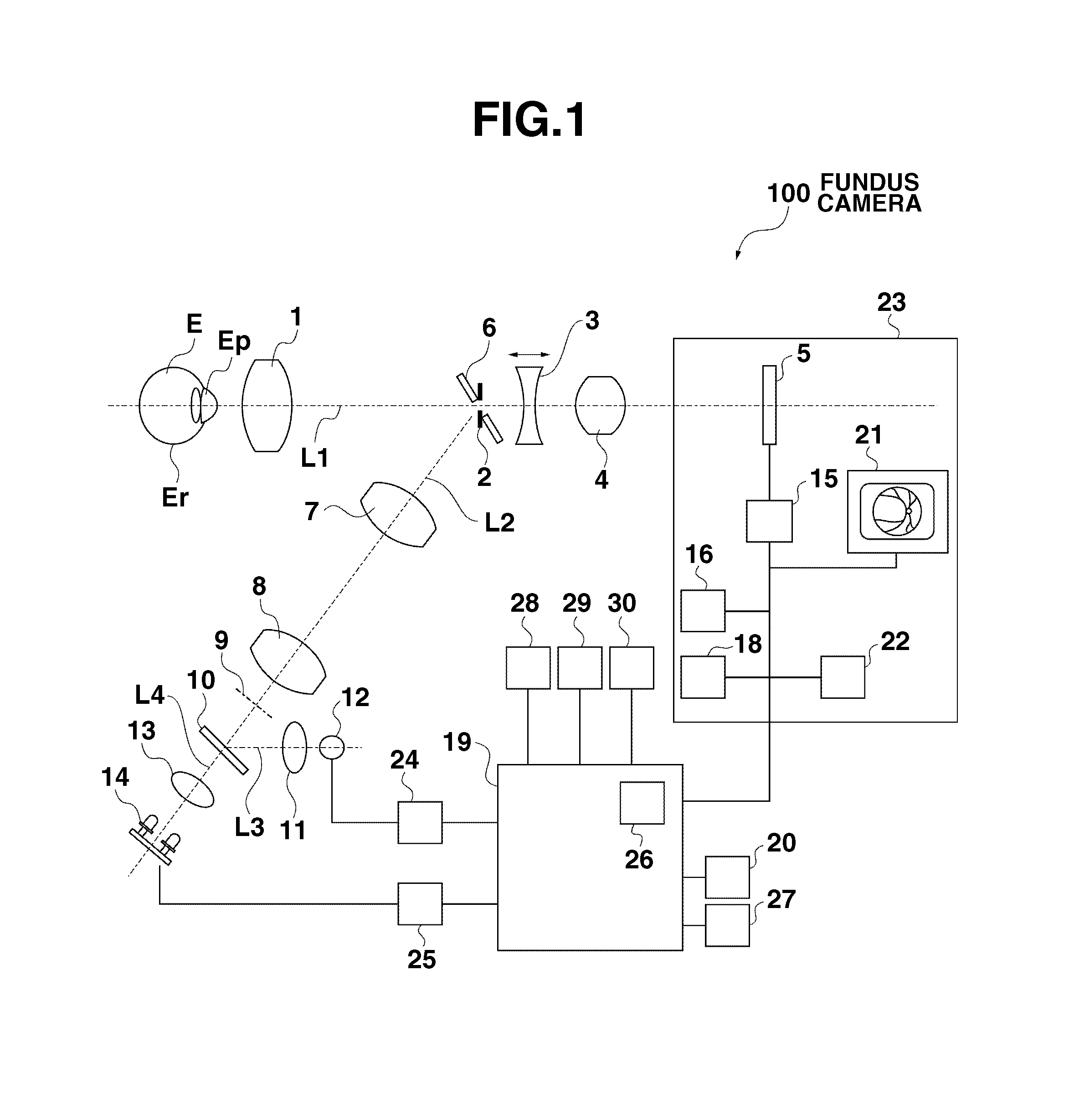
[0022]A configuration of a fundus camera 100, an exemplary ophthalmologic imaging apparatus according to a first exemplary embodiment of the present invention, will be described below with reference to FIG. 1. The fundus camera 100 includes a fundus image observation imaging unit including an observation imaging optical system and an imaging unit 23, a fundus illumination unit including a fundus illumination optical system and a light source, and a central control unit 19.

[0023]The observation imaging optical system includes an object lens 1 disposed facing a subject's eye E, an imaging diaphragm 2 disposed on an optical axis L1 of the object lens 1, and a focal lens 3, and an imaging lens 4. The observation imaging optical system is configured to guide reflected light from the fundus to an image sensor 5. When radiating infrared light, the obs...


PUM


Abstract

An ophthalmologic imaging apparatus includes: a control unit configured to control, based on a pixel value of the optic papilla in an infrared light image of the fundus of a subject's eye to which infrared light is radiated, the light amount of visible light to be radiated onto the subject's eye; and an imaging unit configured to capture an image of the fundus of the subject's eye to which visible light having the controlled light amount is radiated.

Description

BACKGROUND OF THE INVENTION[0001]1. Field of the Invention[0002]The present invention relates to an ophthalmologic imaging apparatus such as a fundus camera which controls the light amount to be received by an image sensor.[0003]2. Description of the Related Art[0004]A conventional ophthalmologic imaging apparatus is known, which radiates imaging light such as visible light onto the fundus of a subject's eye and receives reflected light therefrom to capture a fundus image. Since the reflectance of the fundus differs for each subject's eye because of individual difference and pathological changes, there is provided a technique for suitably controlling the light amount of imaging light to be received by an image sensor.[0005]As an example of such a technique, Japanese Patent Application Laid-Open No. 04-150831 discusses a technique for determining the light amount of visible light (imaging light) based on infrared light radiated onto a subject's eye and reflected by the fundus. Howeve...

Claims


Application Information

Patent Timeline
IPC IPC(8): A61B3/14
CPCA61B3/14
Inventor KAMADA, SHOHHEI
Owner CANON KK
Learn More