Ophthalmologic apparatus and ophthalmologic imaging method

a technology which is applied in the field of ophthalmologic equipment and ophthalmologic imaging methods, can solve problems such as difficulty in accurately detecting alignment indexes, and achieve the effect of accurate detecting alignment indexes regardless

Active Publication Date: 2016-01-12
CANON KK
View PDF14 Cites 0 Cited by
  • Summary
  • Abstract
  • Description
  • Claims
  • Application Information

AI Technical Summary

Benefits of technology

[0009]In view of the aforementioned problems, the invention provides an ophthalmologic apparatus capable of accurately detecting an alignment index regardless of an orientation of an eye to be inspected to automatically perform imaging or automatically adjust the alignment index.
[0012]According to the invention, it is possible to accurately detect the alignment index regardless of the orientation of the eye to be inspected automatically perform imaging, and automatically adjust the alignment index.

Problems solved by technology

As a result, it is difficult to accurately detect the alignment index.

Method used


Image

  • Ophthalmologic apparatus and ophthalmologic imaging method
  • Ophthalmologic apparatus and ophthalmologic imaging method
  • Ophthalmologic apparatus and ophthalmologic imaging method

Examples


first embodiment

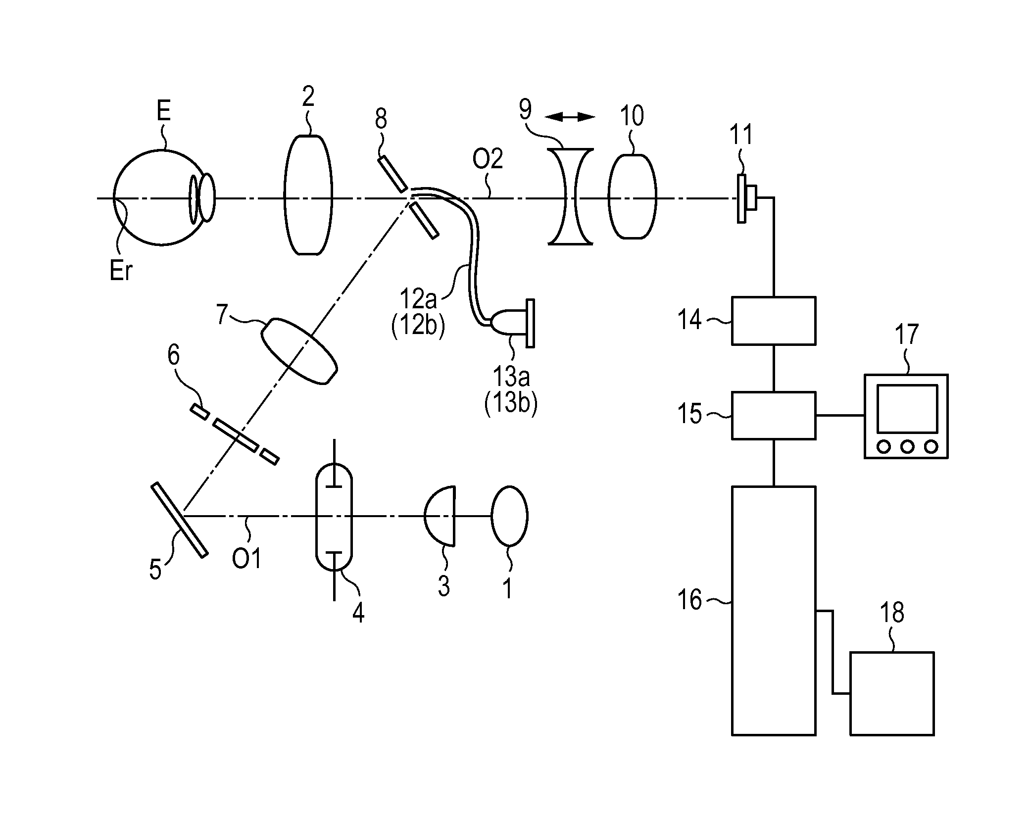
[0023]FIG. 1 is a diagram illustrating a configuration of a fundus camera that is an ophthalmologic apparatus according to a first embodiment of the invention. On an optical path O1 from an observation light source 1 to an objective lens 2 positioned in front of an eye to be inspected E, the observation light source 1, a condenser lens 3, a photographing light source 4, and a mirror 5 are arranged. Moreover, in a reflection direction of the mirror 5, an aperture 6 having a ring-shaped opening, a relay lens 7, and a perforated mirror 8 are sequentially arranged to configure a fundus illumination optical system. In addition, the observation light source includes an LED light source that emits near-infrared light.

[0024]On an optical path O2 behind the perforated mirror 8, a focus lens 9, a photographic lens 10, and an image pickup element 11 including, for example, a CCD, are sequentially arranged to constitute a fundus photographing optical system.

[0025]In addition, at a position devi...

second embodiment

[0047]In this embodiment, instead of the papilla detection unit of the first embodiment configured to automatically detect the papilla, an ophthalmologic examination apparatus has a left / right eye detection unit configured to detect which of the right eye or the left eye is to be inspected and estimates a papilla position from the left / right eye to be inspected.

[0048]In this embodiment, before fundus examination, which of the right eye and the left eye is the eye to be inspected is set using the manipulation section 19 connected to the system control section 16.

[0049]Alternatively, which of the right eye or the left eye is set to as the target eye to be inspected may be determined based on a relative positional relationship between the fundus camera apparatus and the examinee.

[0050]Next, the image processing section configured to detect the alignment state between the eye to be inspected and the apparatus main body will be described with reference to FIG. 4.

[0051]Similar to the firs...

third embodiment

[0061]In this embodiment, in the ophthalmologic apparatus according the second embodiment, fixation position information presented to the examinee is used to determine a papilla position.

[0062]A fixation optical system used in this embodiment will be described. For example, the fixation optical system is disposed on an optical path in behind of the objective lens 2 facing the eye to be inspected E illustrated in FIG. 1. As the fixation optical system, a relay lens, a liquid crystal plate, and a light source are sequentially disposed in behind of the objective lens 2. The liquid crystal plate is used to allow light from the light source to turn on in an arbitrary position for fixing the eye to be inspected E.

[0063]In order to photograph a desired portion of the eye to be inspected E, an operator turns on a desired position of the liquid crystal plate 21. When the desired portion is changed, a lighting position of the liquid crystal plate 21 is moved using a fixation target moving swi...


PUM


Abstract

In order to prevent inaccurate position detection caused by overlapping between a position alignment index and an optic papilla of a fundus in position alignment between an eye to be inspected and an apparatus when a fundus image is photographically captured, an ophthalmologic apparatus includes: a projection unit configured to project a plurality of alignment indices onto an eye to be inspected; an optic papilla position detection unit configured to detect an optic papilla position of the eye to be inspected; and an alignment detection unit configured to detect a positional relation between the eye to be inspected and an apparatus main body from a reflection image of the alignment index, wherein the alignment detection unit performs alignment detection by selecting a reflection image of at least one of the reflection images of the plurality of alignment indices depending on the optic papilla position.

Description

BACKGROUND OF THE INVENTION[0001]1. Field of the Invention[0002]The present invention relates to an ophthalmologic apparatus and an ophthalmologic imaging method.[0003]2. Description of the Related Art[0004]As an ophthalmologic apparatus, there are widely known a fundus camera that photographically captures a fundus of an eye to be inspected. In addition, as the fundus camera, there is known an apparatus that observes the eye to be inspected using a plurality of imaging modes, such as color angiography, visible fluorescent angiography (FAG), or near-infrared indocyanine green (ICG) video angiography, in order to capture an image depending on a purpose of the examination.[0005]When the fundus camera is used to capture an image, it is necessary to delicately adjust a working distance between the eye to be inspected and the fundus camera. Therefore, an alignment index is projected onto the eye to be inspected, and alignment adjustment is performed using the index image.[0006]In Japanes...

Claims


Application Information

Patent Timeline
Patent Type & Authority Patents(United States)
IPC IPC(8): A61B3/14A61B3/15
CPCA61B3/152
Inventor ONO, MITSUHIRO
Owner CANON KK
Why Eureka
Try Eureka