
Pulse wave transmission detection system

a detection system and pulse wave technology, applied in the field of pulse wave propagation detection system, can solve problems such as general malaise, lightheadedness, and general malaise, and achieve the effect of convenient and accurate measuring of blood flow in the brain

Inactive Publication Date: 2010-02-23
BML INC
View PDF3 Cites 0 Cited by
  • Summary
  • Abstract
  • Description
  • Claims
  • Application Information

AI Technical Summary

Benefits of technology

"The present invention is about a system and method for detecting pulse waves in the brain using an eyeground image and an electrocardiographic signal. The system can accurately measure the diameter of an eyeground vein, which is connected to the cerebral circulatory system, and can detect changes in the vein caused by the pulsation of the vein. This allows for the monitoring of blood flow in the brain. The system can also detect the state of sclerosis of a capillary artery, which is a marker for cerebral arteriosclerosis. The system uses an eyeground image detection system that synchronizes with an electrocardiographic signal, which is detected using electrodes mounted on the chest or other site of the subject. The electrocardiographic signal can be any established pattern of an electrocardiogram, such as a P wave, a Q wave, an R wave, an S wave, or a T wave. The technical effects of the invention include accurate and convenient monitoring of blood flow in the brain and detection of changes in the state of sclerosis of a capillary artery."

Problems solved by technology

However, hypotension is known to cause various symptoms, including dizziness, light-headedness, and general malaise.
Particularly, in the elderly, there is concern about accidents caused by light-headedness, or progress of dementia, which could occur as a result of reduction of pulse wave propagation through intracerebral blood vessels.

Method used


Image

  • Pulse wave transmission detection system
  • Pulse wave transmission detection system
  • Pulse wave transmission detection system

Examples


Embodiment Construction

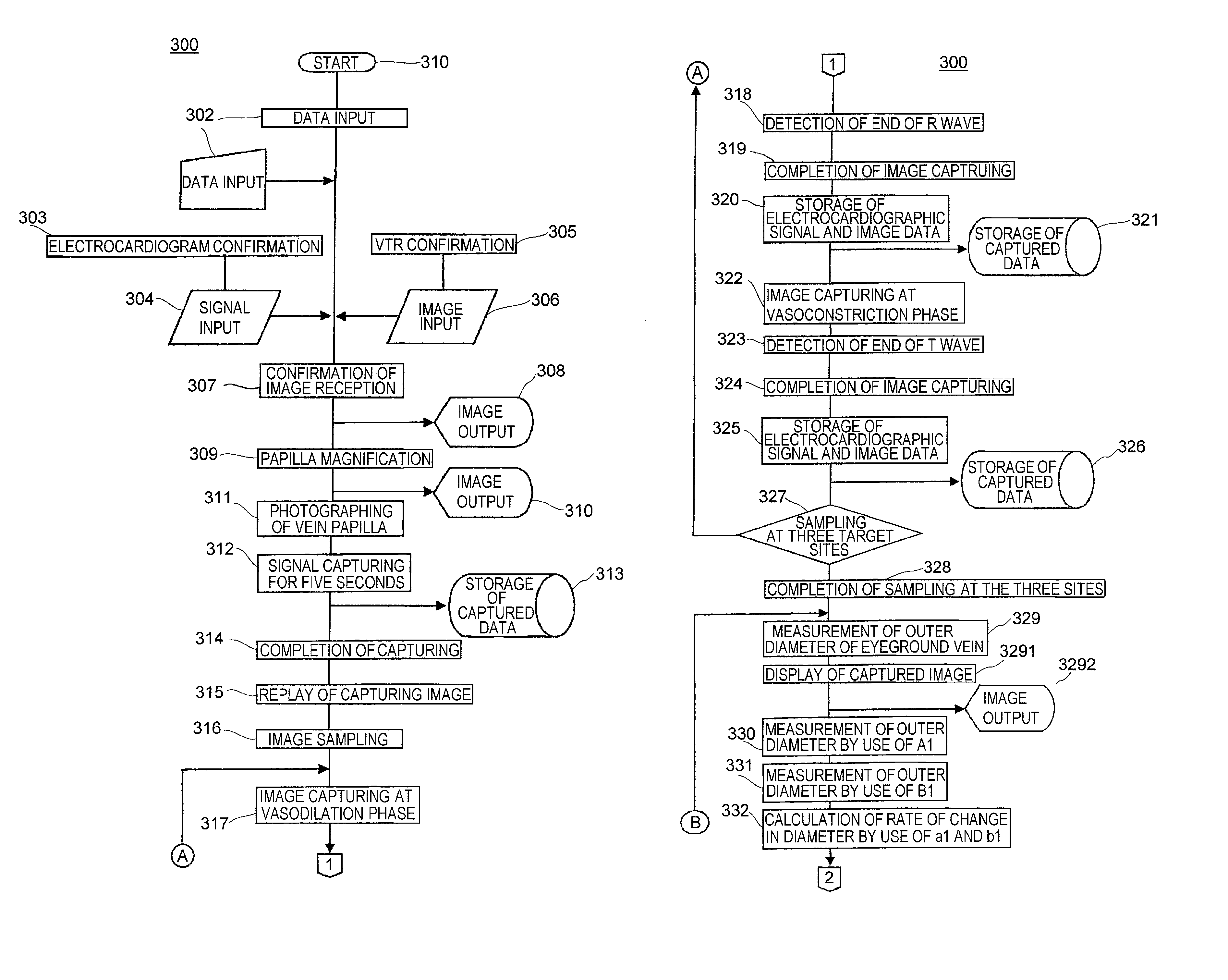
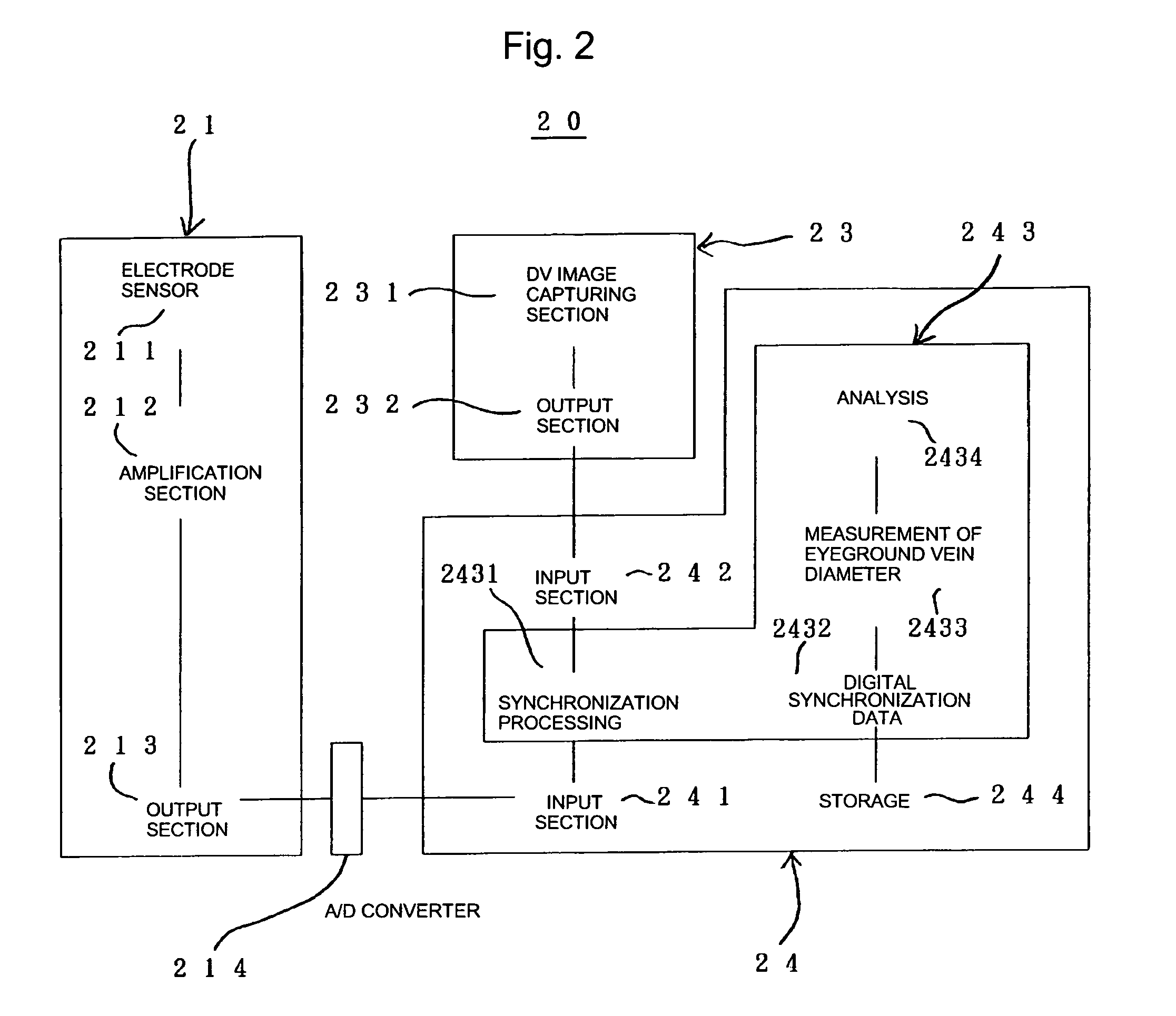
[0073]Embodiments of the present invention will next be described with reference to the appended drawings.

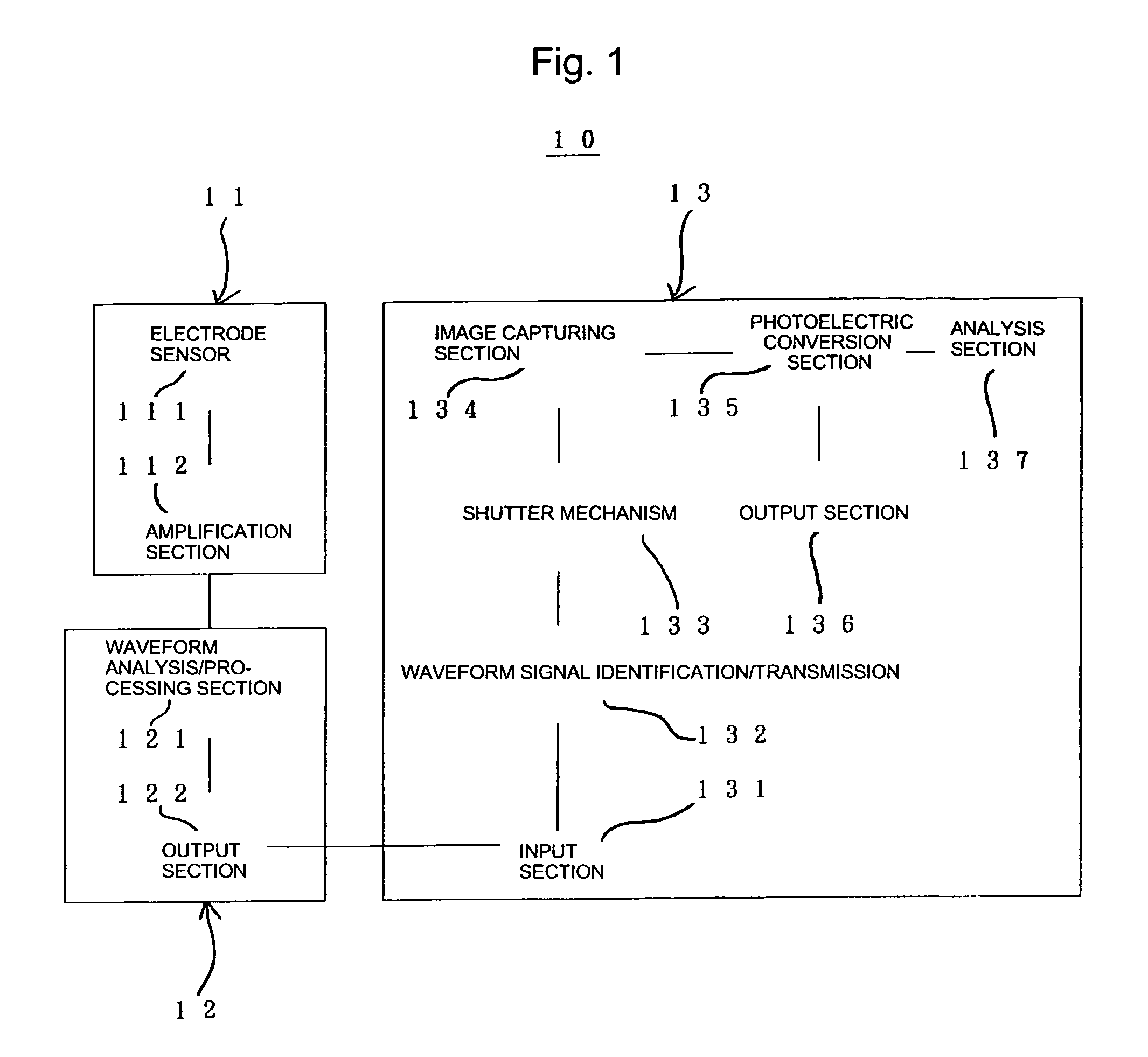
[0074]FIG. 1 is a block diagram showing the configuration of an embodiment of the eyeground image detection system employed for implementing the present detection system.

[0075]As shown in FIG. 1, the detection system of the present invention 10 includes an electrocardiographic signal detection unit 11, an electrocardiographic signal identification unit 12, and an eyeground image detection unit 13.

[0076]The electrocardiographic signal detection unit 11 includes an electrode sensor 111 and an amplification section 112. The electrocardiographic signal identification unit 12 includes a waveform analysis / processing section 121 and an output section 122. The eyeground image detection unit 13 includes an input section 131, a waveform signal identification / transmission section 132, a shutter mechanism 133, an image capturing section 134, a photoelectric conversion section 135, an output...


PUM


Abstract

Provided is a pulse wave propagation detection system including an electrocardiographic signal detection unit, and an eyeground image detection unit for detecting an eyeground image in synchronization with an electrocardiographic signal detected through the detection unit, which system further includes a correlation unit for correlating a change in the diameter of an eyeground vein—which diameter is measured, at the optic papilla, by use of an eyeground image synchronized with an arbitrary electrocardiographic signal—with the state of pulse wave propagation through an intracerebral blood vessel or with the state of sclerosis of a capillary artery.

Description

TECHNICAL FIELD[0001]The present invention relates to a pulse wave propagation detection system.BACKGROUND ART[0002]Monitoring loss or considerable reduction of pulsation in capillary blood vessels is considered to be important for the maintenance of health conditions.[0003](1) Approach to Hypotension[0004]In general, the term “hypotension” refers to the case where maximum blood pressure is 110 to 100 mmHg or less. Hypotension is classified into the following types: “essential hypotension,” with which no causative disease is found; “orthostatic hypotension”; i.e., a fall in blood pressure that occurs when a person suddenly rises from a recumbent position or stands up, which may cause, for example, dizziness or light-headedness; and “symptomatic hypotension,” which is caused by some disease (e.g., diabetes).[0005]Less attention has been drawn to hypotension as compared with hypertension, which is also a pathological condition related to blood pressure. However, hypotension is known t...

Claims


Application Information

Patent Timeline
Patent Type & Authority Patents(United States)
IPC IPC(8): A61B5/02G06K9/00A61B3/12A61B5/0402
CPCA61B3/1241A61B5/0402A61B5/318A61B5/33
Inventor KAWADA, REIJITAKANO, SYOICHI
Owner BML INC
Learn More