Simplex connectors for multicore optical fiber cables

a multi-core, fiber optic technology, applied in the field of fiber optics, can solve the problems of high-density configurations assembled using standard single-core fibers that are extremely expensive to produce, mt ferrules are very expensive to produce, and the production yield of mt ferrules on 2-d-arrays leads to significantly higher cost. , to achieve the effect of precise rotational alignment of multi-core fibers

Active Publication Date: 2011-09-22
OFS FITEL LLC
View PDF24 Cites 72 Cited by
  • Summary
  • Abstract
  • Description
  • Claims
  • Application Information

AI Technical Summary

Benefits of technology

[0011]An aspect of the invention provides an optical fiber cable connector. In a ferrule subassembly, a ferrule is mounted into a receptacle including a barrel section having a flange at its base. The ferrule subassembly is loaded into an enclosure having a plug housing at its lead end. The plug housing is configured to provide a connection between an endface of a multicore fiber, mounted into the ferrule, and an optical transmission device having a mating socket. Alternately, the multicore fiber could be connected to another multicore fiber, via a pass-through adapter, with connectors installed into opposing ends of the adapter. A collar is ro

Problems solved by technology

However, high-density configurations assembled using standard single-core fibers have proven to be extremely expensive to produce, since achieving physical contact between all of the fibers, when two connectors are mated, requires very precise control of the polishing process to ensure coplanarity (especially in the 72-fiber variant).
Also, the molded MT ferrules are very expensiv

Method used


Image

  • Simplex connectors for multicore optical fiber cables
  • Simplex connectors for multicore optical fiber cables
  • Simplex connectors for multicore optical fiber cables

Examples


Embodiment Construction

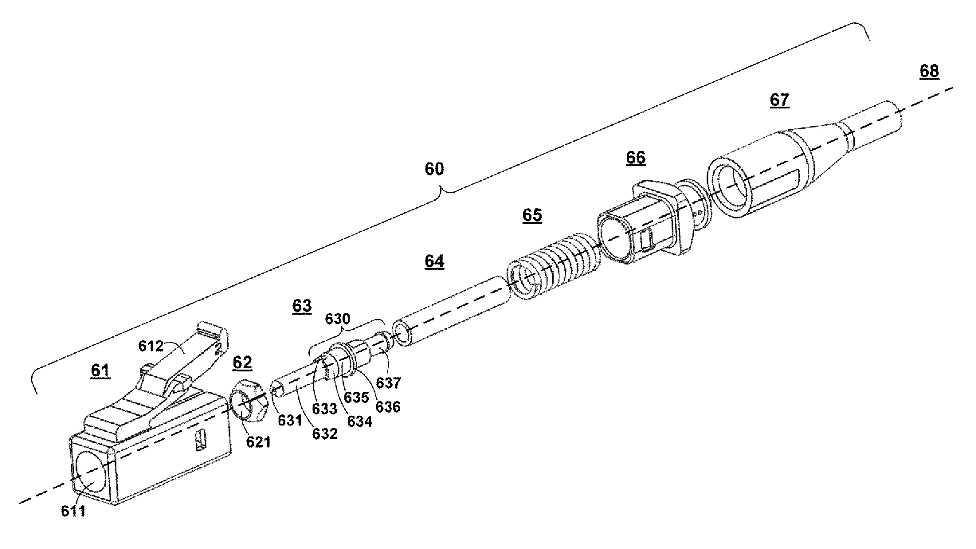
[0057]Aspects of the invention are directed to simplex (i.e., single-fiber) connectors for use with single-mode and multimode multicore fibers. As discussed below, a connector of the type described herein is mounted to the end of a multicore fiber cable. The connector provides plug-in connectivity between the multicore fiber cable and an optical transmission device having a mating socket. When the connector is plugged into the socket, an endface of the cabled multicore fiber is urged against a corresponding surface within the socket. Alternately, the multicore fiber could be connected to another multicore fiber, via a pass-through adapter, with connectors installed into opposing ends of the adapter.

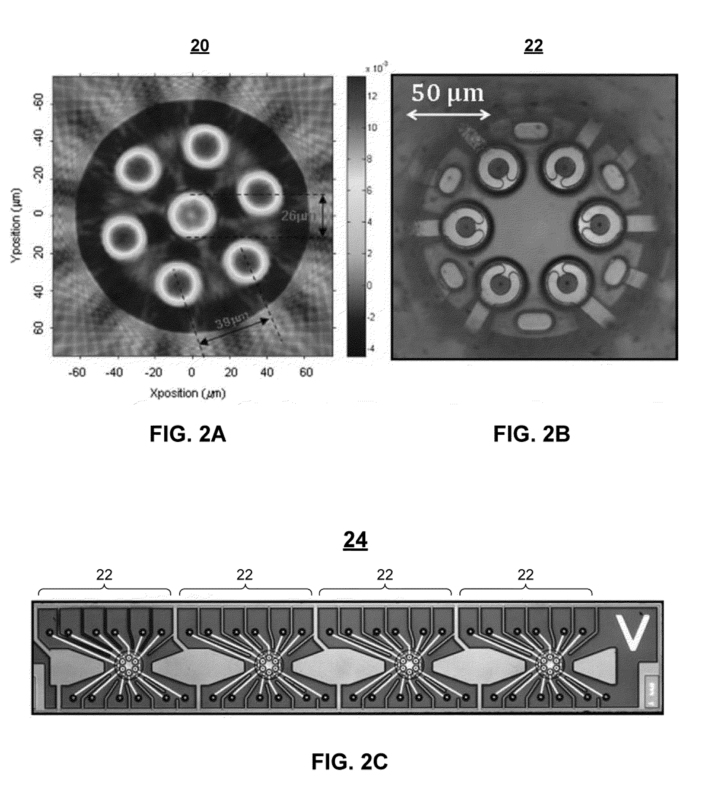
[0058]One application for simplex connectors of the type described herein is in a multi-channel transmission system, in which segments of multicore fiber are butt-coupled with specially designed 2-dimensional VCSEL and PiN photo detector arrays to facilitate simultaneous transmission over...


PUM

PropertyMeasurementUnit
Lengthaaaaaaaaaa
Forceaaaaaaaaaa
Lengthaaaaaaaaaa

Abstract

An optical fiber cable connector includes a ferrule subassembly, in which a ferrule is mounted into a receptacle including a barrel section having a flange at its base. The ferrule subassembly is loaded into an enclosure having a plug housing at its lead end. The plug housing is configured to provide a connection between an endface of a multicore fiber mounted into the ferrule and a corresponding surface in a mating socket. A collar is rotatably mounted onto the barrel section of the ferrule subassembly such that it butts up against the flange. The collar has an opening that fits around the barrel section, and an outer perimeter that fits into a receiving cavity with the plug housing. The ferrule, receptacle, receptacle barrel section, mounted multicore fiber, enclosure, and plug housing have a common longitudinal axis. As a result, the ferrule, receptacle, receptacle barrel section, and mounted multicore fiber are continuously rotatable with respect to the enclosure and plug housing, thereby enabling a precise rotational alignment of the multicore fiber within the enclosure.

Description

CROSS REFERENCE TO RELATED APPLICATIONS[0001]The present application claims the priority benefit of the following U.S. provisional patent applications, which are owned by the assignee of the present application, and which are incorporated herein by reference in their entirety:[0002]U.S. Prov. Pat. App. Ser. No. 61 / 314,165, filed on Mar. 16, 2010.BACKGROUND OF THE INVENTION[0003]1. Field of the Invention[0004]The present invention relates generally to the field of fiber optics, and in particular to improved simplex connectors for multicore optical fiber cables.[0005]2. Background Art[0006]The ever increasing demand for high-density, high-speed parallel optical data links, for super-computer and data-center applications, has spawned significant interest in passive optical devices designed to facilitate reliable, cost-effective deployment. In multi-channel parallel links for super computers and data centers, thousands of optical links, operating at 1 Gb / s to 10 Gb / s, may be utilized.[0...

Claims


Application Information

Patent Timeline
IPC IPC(8): G02B6/36G02B6/25
CPCG02B6/3851G02B6/3885G02B6/3893Y10T29/49895G02B6/02042Y10T29/49174G02B6/4403G02B6/3871Y10T156/1052G02B6/245G02B6/3834G02B6/3843G02B6/3861G02B6/3863
Inventor BRADLEY, KELVIN B.SANDELS, GREGORY A.WHITE, WILLARD C.
Owner OFS FITEL LLC
Why Eureka
Try Eureka