
Control system simulator and simplified interconnection control system

a control system and simulator technology, applied in the field of simulators, can solve the problems of reducing affecting the so as to facilitate remote configuration and operation of the control system, simplify the electrical interconnection, and reduce the number of hardware components required

Inactive Publication Date: 2011-09-22
X 10
View PDF47 Cites 28 Cited by
  • Summary
  • Abstract
  • Description
  • Claims
  • Application Information

AI Technical Summary

Benefits of technology

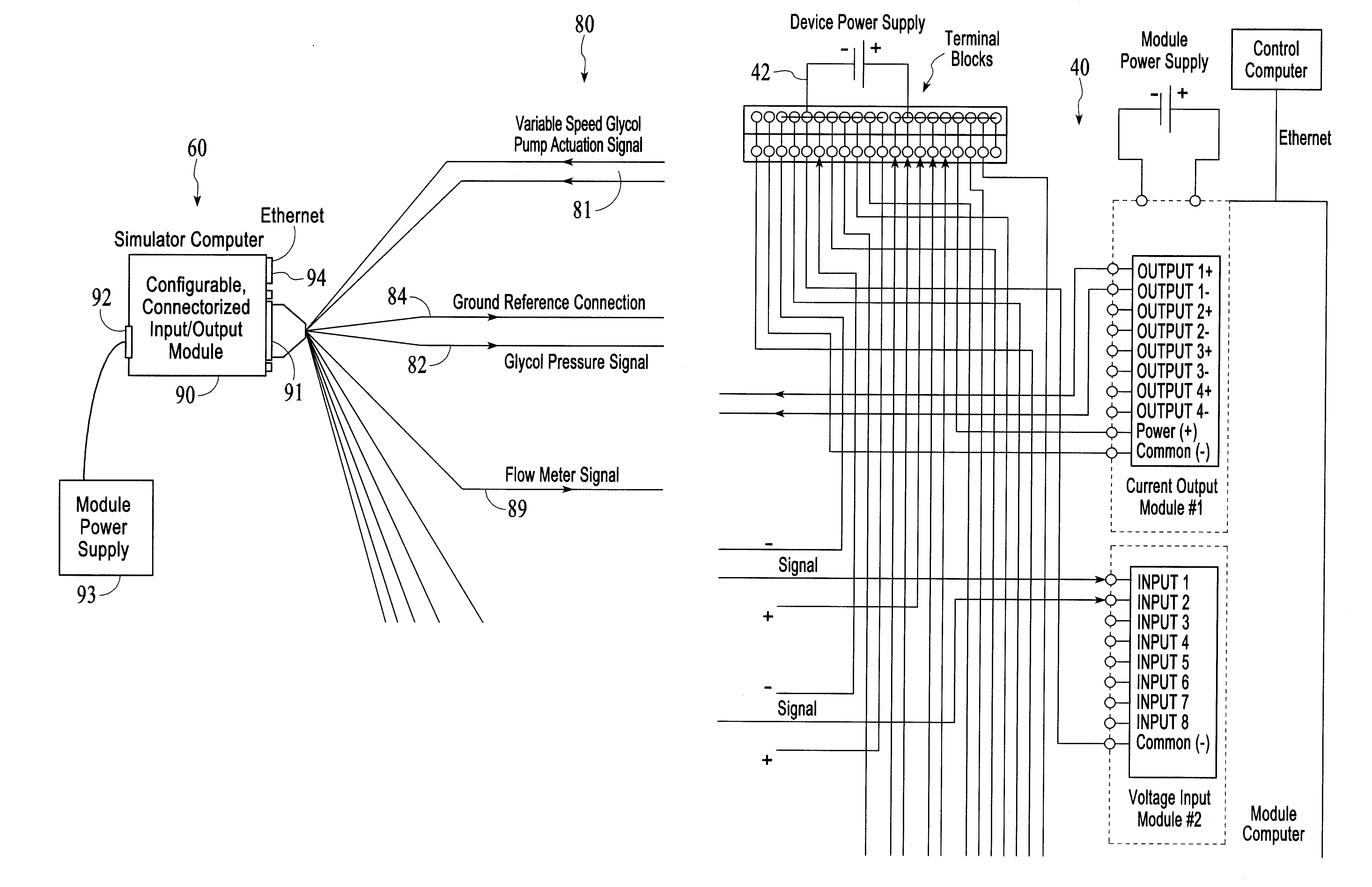
[0009]The present invention provides a computer-based simulator that is separate from the computer control system. The invention simplifies the electrical interconnection of the computer-based simulator to the computer control system and reduces the number of hardware components required to effect a computer-based simulator. The invention also facilitates remote configuration and operation of the control and simulator systems.

Problems solved by technology

Such a simple simulation is commonly used but suffers from several limitations.
Second, the simulated value might not be a good representation of the physical value.
Thus, this simple modified software simulation strategy of embedding software into the control system suffers from significant limitations.
The prior art strategy of employing a second computer to simulate the process, although effective, is itself complex and expensive because the complexity of the simulator is roughly equal to the complexity of the tool control system.
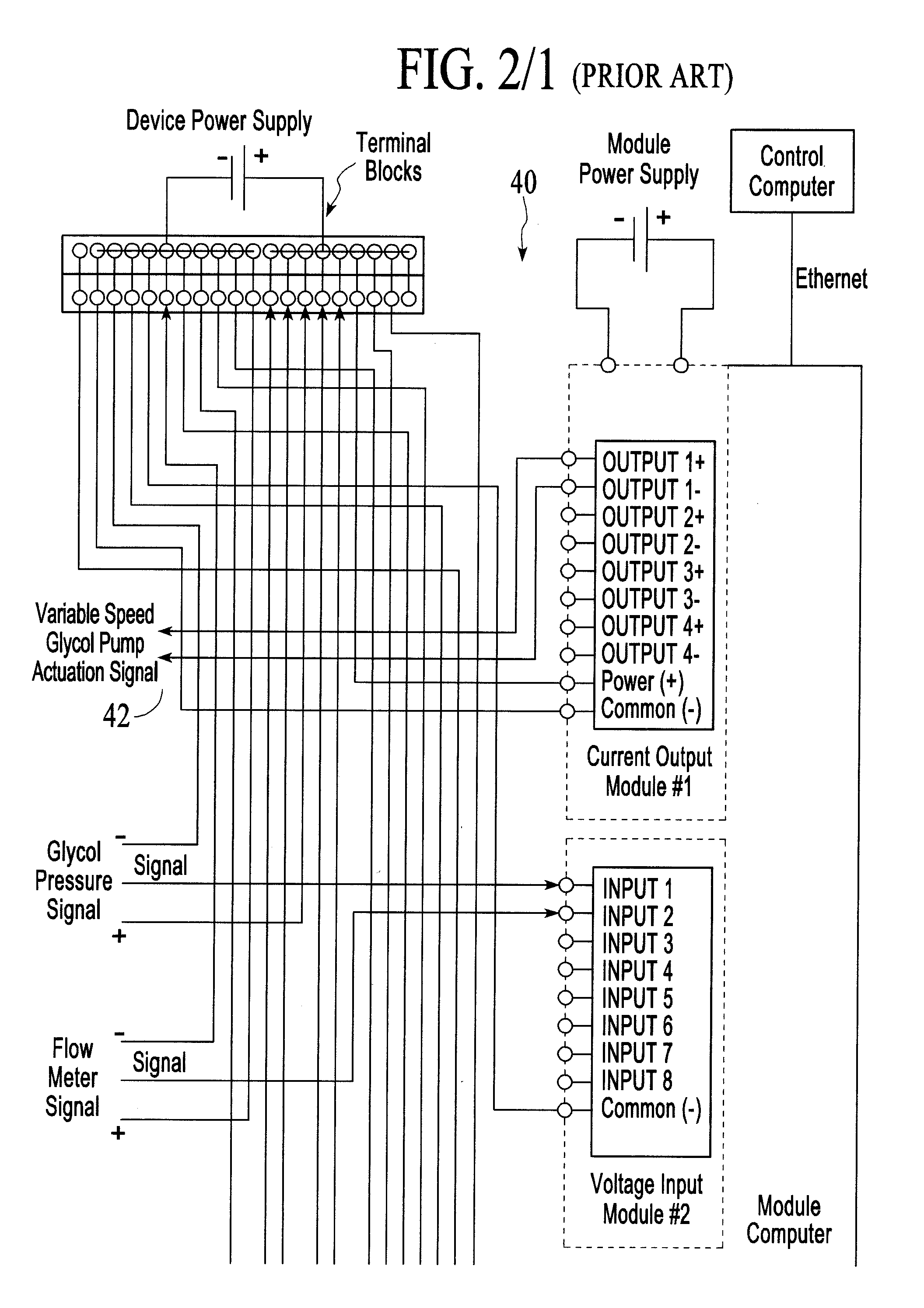
In addition, the second simulator computer must be electrically connected to the tool control system, and the connections are complex, error prone and time consuming.

Method used


Image

  • Control system simulator and simplified interconnection control system
  • Control system simulator and simplified interconnection control system
  • Control system simulator and simplified interconnection control system

Examples


Embodiment Construction

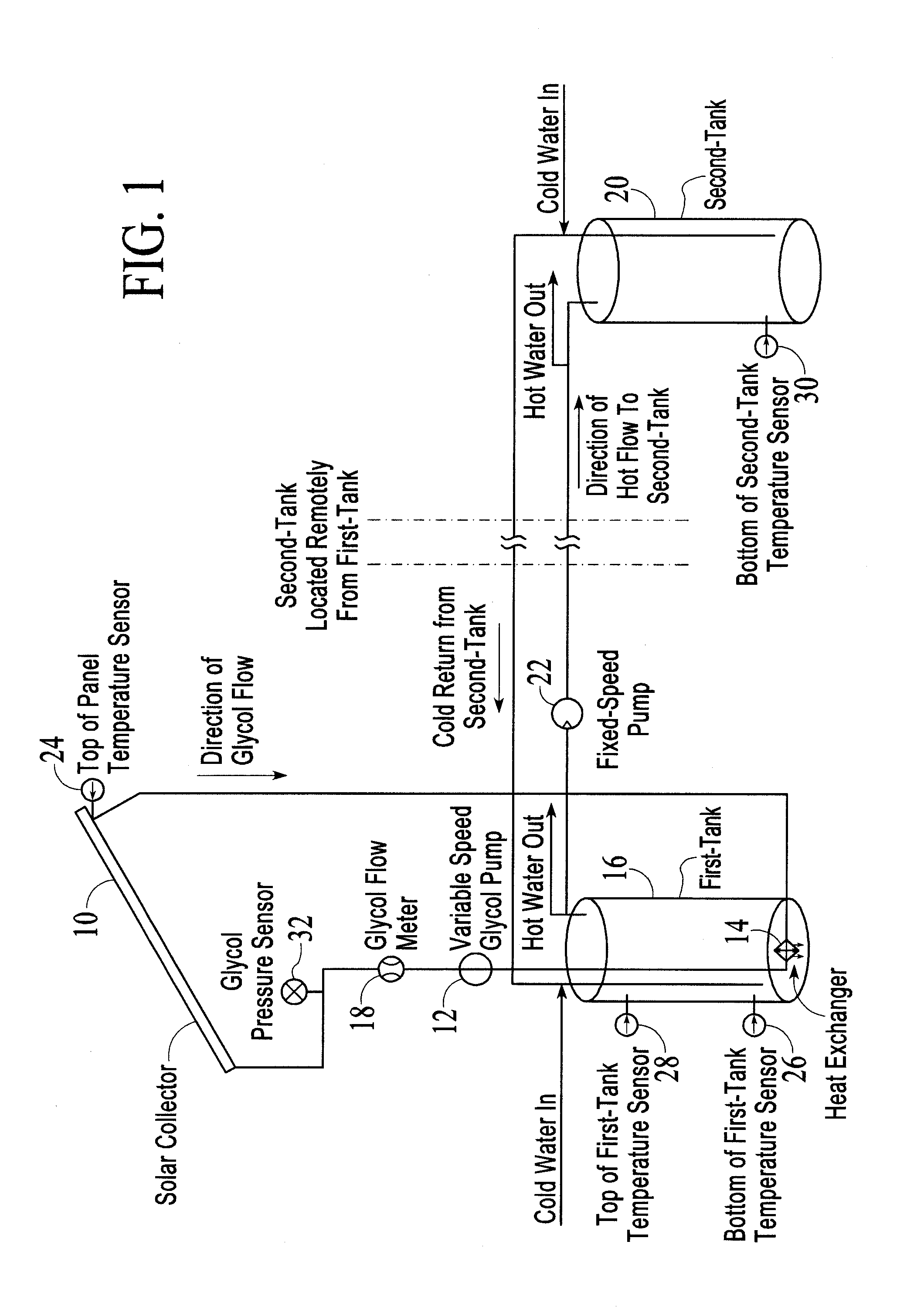
[0022]In U.S. Pat. Nos. 6,892,265, 7,216,191 and 7,822,896, a method and apparatus is described which provides for a configurable, connectorized module to be employed to effect an input / output and control system capable of interfacing to sensors and actuators. Such a module can perform the functions of an input / output system or a control system, using sensor information to compute actuation signals which are then connected to actuators. Modules built using the teaching of these inventions have been employed as input / output systems for control systems or as a control system for a variety of processes. Thus, temperature sensors may be electrically connected to the module and heater actuation signals may be connected electrically to a heater system. Such modules have demonstrated the ability to reduce the number of components required to build a control system while significantly reducing the complexity of the interconnection wiring.

[0023]Although a simulator computer functions in a ve...


PUM


Abstract

A computer-based simulator, separate from a computer process control system, that simplifies the electrical interconnection of the computer-based simulator to the computer control system and reduces the number of hardware components required to effect a computer-based simulator. The invention also facilitates remote configuration and operation of the control and simulator systems.

Description

RELATED APPLICATIONS[0001]This application claims the benefit of U.S. Provisional Patent Application Ser. No. 61 / 316,070 filed Mar. 22, 2010, and is a continuation-in-part of U.S. patent application Ser. No. 12 / 911,445 filed Oct. 25, 2010, which is a continuation of U.S. patent application Ser. No. 12 / 106,968 filed Apr. 21, 2008 (now U.S. Pat. No. 7,822,896 and which claims the benefit of U.S. Provisional Application Ser. No. 60 / 950,040 filed Jul. 16, 2007), which is a continuation-in-part of U.S. patent application Ser. No. 11 / 801,127 filed May 7, 2007 (now abandoned), which is a continuation of U.S. patent application Ser. No. 11 / 296,134 filed Dec. 6, 2005 (now U.S. Pat. No. 7,216,191), which is a continuation-in-part of U.S. patent application Ser. No. 11 / 043,296 filed Jan. 25, 2005 (now abandoned), which is a continuation-in-part of U.S. patent application Ser. No. 10 / 071,870 filed Feb. 8, 2002 (now U.S. Pat. No. 6,892,265 and which claims the benefit of U.S. Provisional Applica...

Claims


Application Information

Patent Timeline
IPC IPC(8): G06G7/62
CPCG05B17/02G06F30/20
Inventor SAGUES, PAUL
Owner X 10
Learn More