
Storage tank floating roof sump with emergency overflow

Active Publication Date: 2011-09-29
SAUDI ARABIAN OIL CO
View PDF20 Cites 1 Cited by
  • Summary
  • Abstract
  • Description
  • Claims
  • Application Information

AI Technical Summary

Benefits of technology

[0011]It is therefore an object of the present invention to provide an apparatus for effectively and reliably draining accumulated rain water from a floating roof on a liquid product tank by a self-opening emergency overflow apparatus to provide adequate drainage if the primary drainage system fails.
[0012]A further object is to prevent weight overload on the floating roof which could damage, break or sink its by providing emergency drainage if and when the primary drainage system fails.
[0015]Another object of the invention is to provide an apparatus for draining accumulated rain water from the top of a roof on a liquid product tank while also reduces product evaporation losses to the atmosphere.
[0016]A further object of the invention is to provide an automatic roof drain apparatus that is of simple and rugged construction and inexpensive to manufacture and install.IV. SUMMARY OF THE INVENTION

Problems solved by technology

The water will therefore rise and can inundate the drain sealing mechanism.
Also, the presence of debris carried by the accumulating water can interfere with proper operation of complex roof drain apparatus known to the prior art.
A further problem can occur when rainwater accumulates on the roof and its effective weight increases to a point where it can overcome the buoyancy of the roof, eventually forcing it into the liquid in the tank.
The valve is again closed when the depth of the water on the roof decreases until it is no longer sufficient to hold the valve open against the buoyancy force of the float.
Still other prior art patents disclosing aspects of floating roofs and drainage systems are U.S. Pat. Nos. 2,563,017; 2,664,5220; 4,134,515; 4,202,366; 3,944,113 and US 2007 / 0272692; however, these prior art patents do not disclose a system the same as or equivalent to the present emergency drainage system described below.
The above discussed prior art systems for draining water from floating roofs do not overcome the problems of reliability, performance under extreme conditions and secure sealing of the drain opening associated with floating roofs.
Unfavorable weather conditions, such as high winds and a significant accumulation of rainwater, may cause the roof to sink or become damaged.
Another problem to be considered is evaporation losses of liquid product stored in the tank.

Method used


Image

  • Storage tank floating roof sump with emergency overflow
  • Storage tank floating roof sump with emergency overflow
  • Storage tank floating roof sump with emergency overflow

Examples


Embodiment Construction

[0051]To facilitate an understanding of the invention, the same reference numerals have been used, when appropriate, to designate the same or similar elements that are common to the figures. Unless stated otherwise, the features shown and described in the figures are not drawn to scale, but are shown for illustrative purposes only.

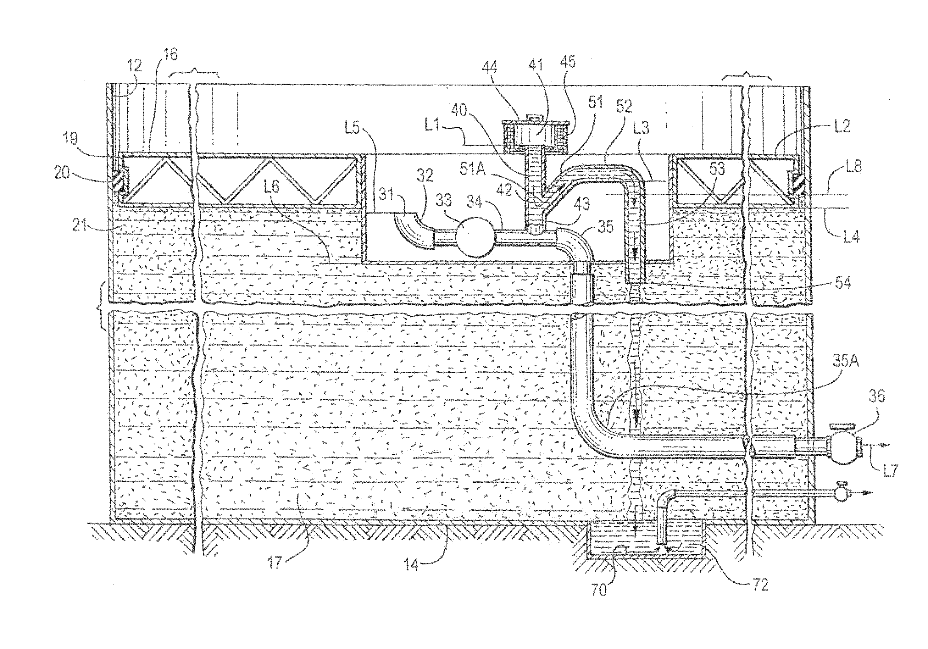
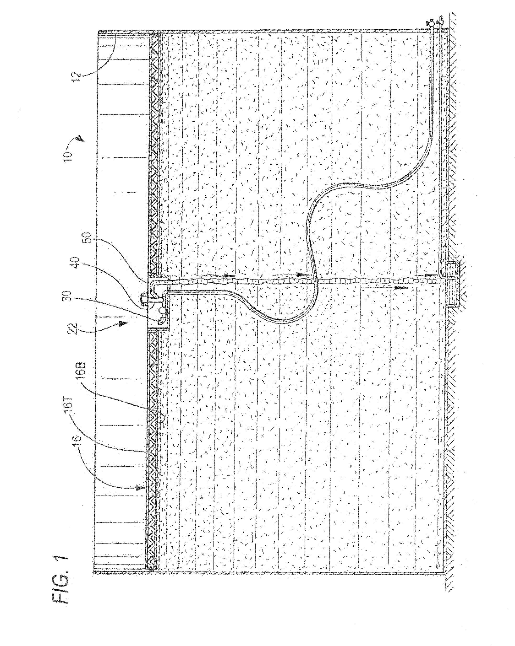
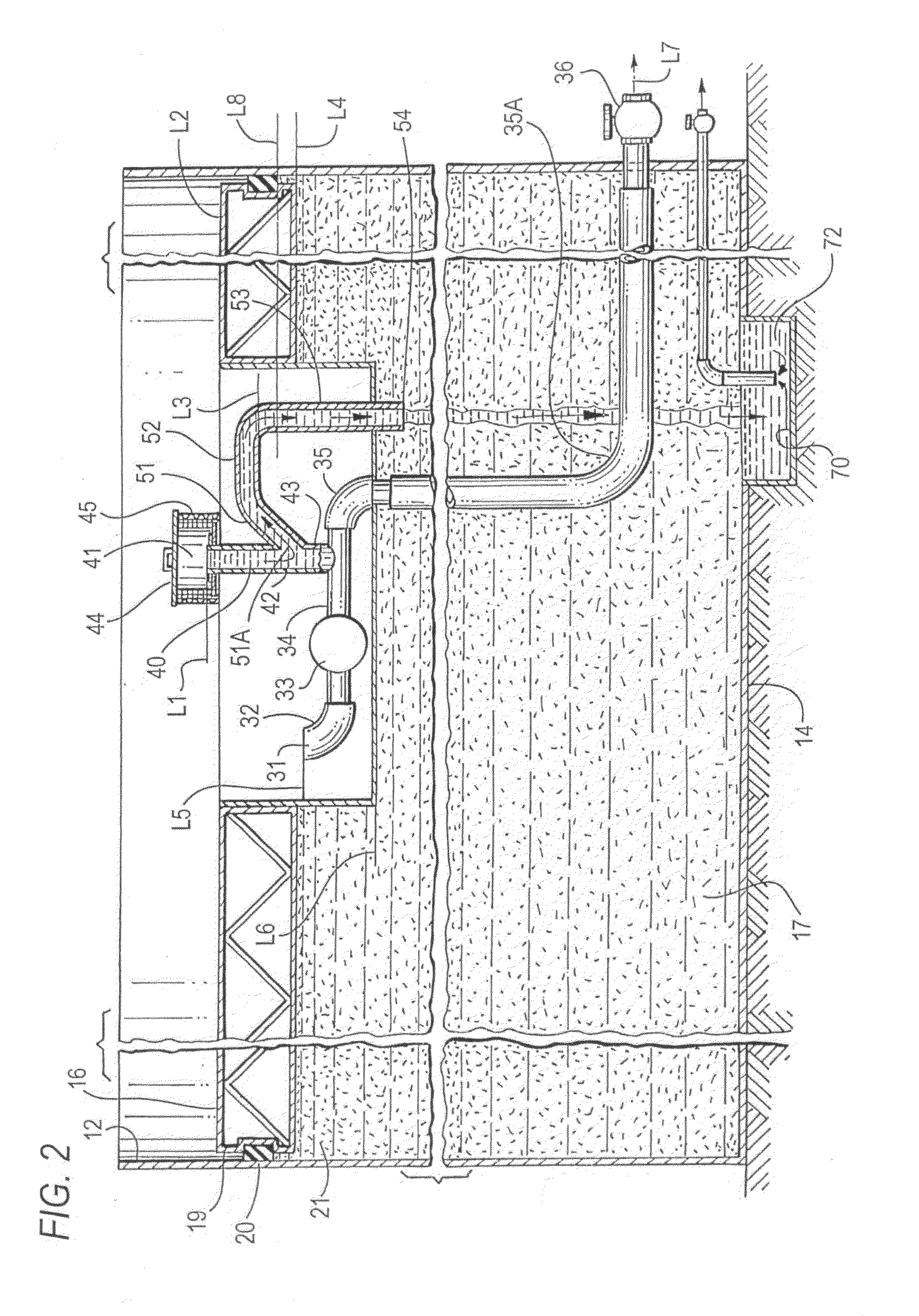
[0052]FIG. 1 shows storage tank 10 formed of cylindrical side walls 12, bottom 14 and floating roof 16, having top surface 16T and bottom surface 16B, intended primarily for containing a liquid petroleum product 17 that varies in quantity within tank 10 and on which roof 16 floats. Between the roof's peripheral edges 19 and he storage tank side walls 12 is a seal element 20 that seals the circumferential gap from upward flowing fumes 21 between said side walls 12 and peripheral edge 19, while allowing roof 16 to move upward and downward as it floats on liquid product 17. Shown schematically in roof 16 is sump 22.

[0053]As discussed earlier, the concern with...


PUM

PropertyMeasurementUnit
Angleaaaaaaaaaa
Flow rateaaaaaaaaaa
Shapeaaaaaaaaaa

Abstract

A floating roof and emergency overflow drainage system for water accumulated on the floating roof which is adapted to cover a liquid storage tank containing a liquid product, the tank adapted to contain the liquid product up to a predetermined maximum level on the roof's top surface, comprising:a. a water collection sump formed as a downward extending recess in the top surface of the roof and adapted to receive water accumulated atop the roof,b. a first drainage duct having an inlet within the water collection sump at an elevation below the top surface of the roof, an outlet for draining water at an elevation below the sump, and an intermediate portion extending transversely between the inlet and the outlet,c. a second drainage duct having an inlet above the top surface of the roof, an intermediate portion extending downwardly from the inlet, and an outlet in fluid communication with the intermediate portion of the first duct in the sump, andd. an emergency overflow duct including:(1) an inlet in fluid communication with the second duct,(2) a proximal portion extending upwardly from the inlet,(3) a medial portion extending transversely from said proximal portion at an elevation above the level of the stored liquid, and(4) a distal portion extending downwardly from the medial portion and terminating in an outlet below the sump and in the stored liquid.

Description

I. FIELD OF THE INVENTION[0001]The present invention relates to a drainage device for use on a floating roof on a storage tank for liquid products.II. BACKGROUND OF THE INVENTION[0002]Storage tanks for oil and other liquid hydrocarbon products are typically provided with a floating roof. The floating roof moves vertically on the surface of the liquid product to prevent the escape of harmful vapors. A typical floating roof for covering a liquid product in a storage tank includes a deck whose peripheral side edges substantially conform to the horizontal cross-sectional shape of the storage tank. The roof has a vertical thickness and is provided with one or more seals extending between the outer periphery of the floating roof and the inner wall of the tank. The roof floats on top of the stored liquid product and rises and falls as the amount of the liquid product increases and decreases. It is known to provide a drain pipe extending vertically through the top surface of deck to drain w...

Claims


Application Information

Patent Timeline
IPC IPC(8): B65D88/34B65D88/38B23P19/04
CPCB65D88/38Y10T29/53B65D88/34
Inventor BEN AFEEF, MOHAMMED A.
Owner SAUDI ARABIAN OIL CO
Learn More