
Overflow drainage system for floating roof storage tank

a floating roof and drainage system technology, applied in the direction of containers, packaging, building components, etc., can solve the problems of inconvenient installation, inundation of the drain sealing mechanism, and interference with the proper operation of the complex roof drain apparatus, etc., to achieve the effect of simple and rugged construction, inexpensive manufacturing and installation

Active Publication Date: 2008-07-03
SAUDI ARABIAN OIL CO
View PDF24 Cites 6 Cited by
  • Summary
  • Abstract
  • Description
  • Claims
  • Application Information

AI Technical Summary

Benefits of technology

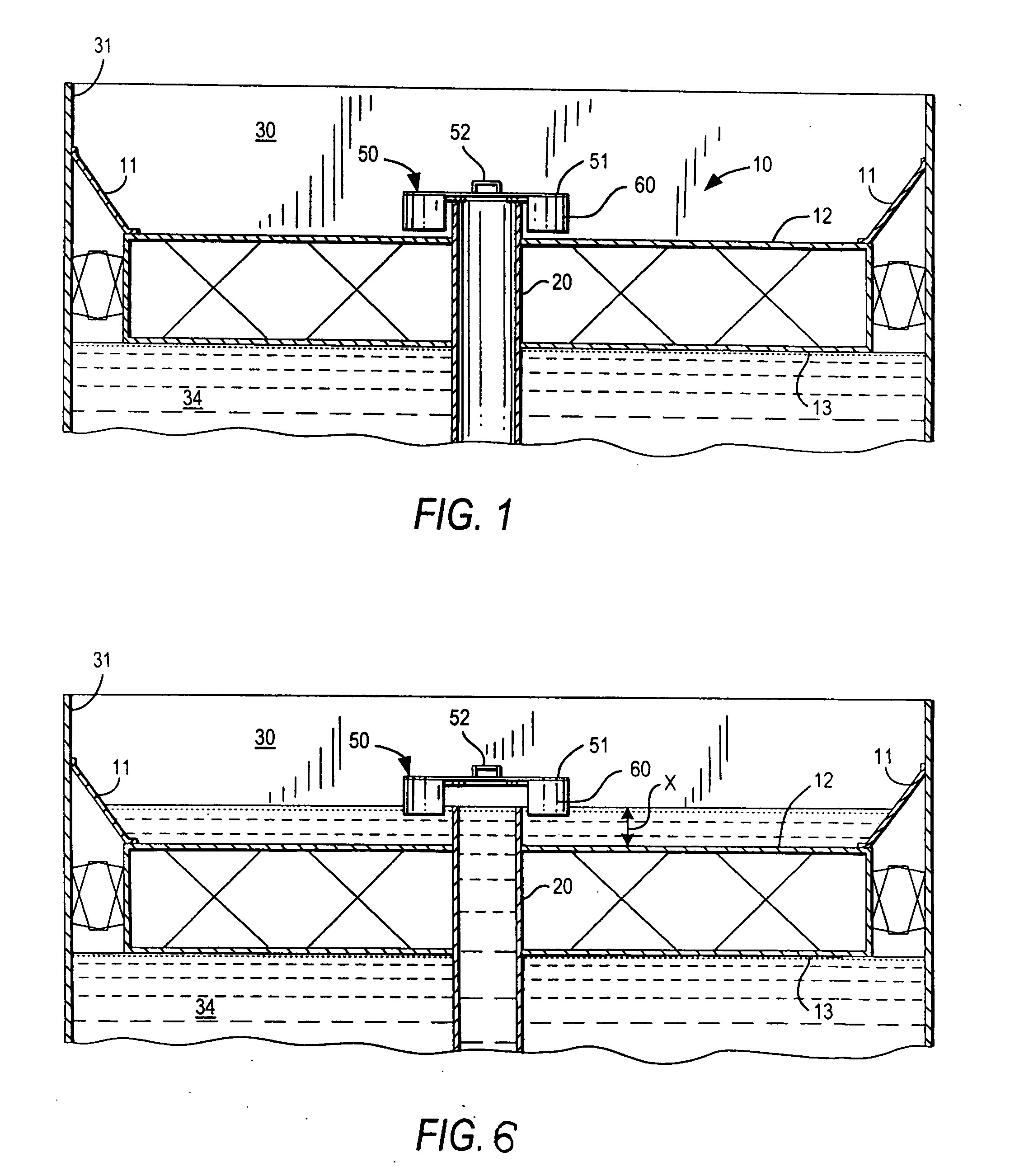
[0018]The drain pipe preferably extends into, and terminates below the surface of the liquid in the tank in order to minimize the amount of vapors that might be displaced from the tank into the environment.
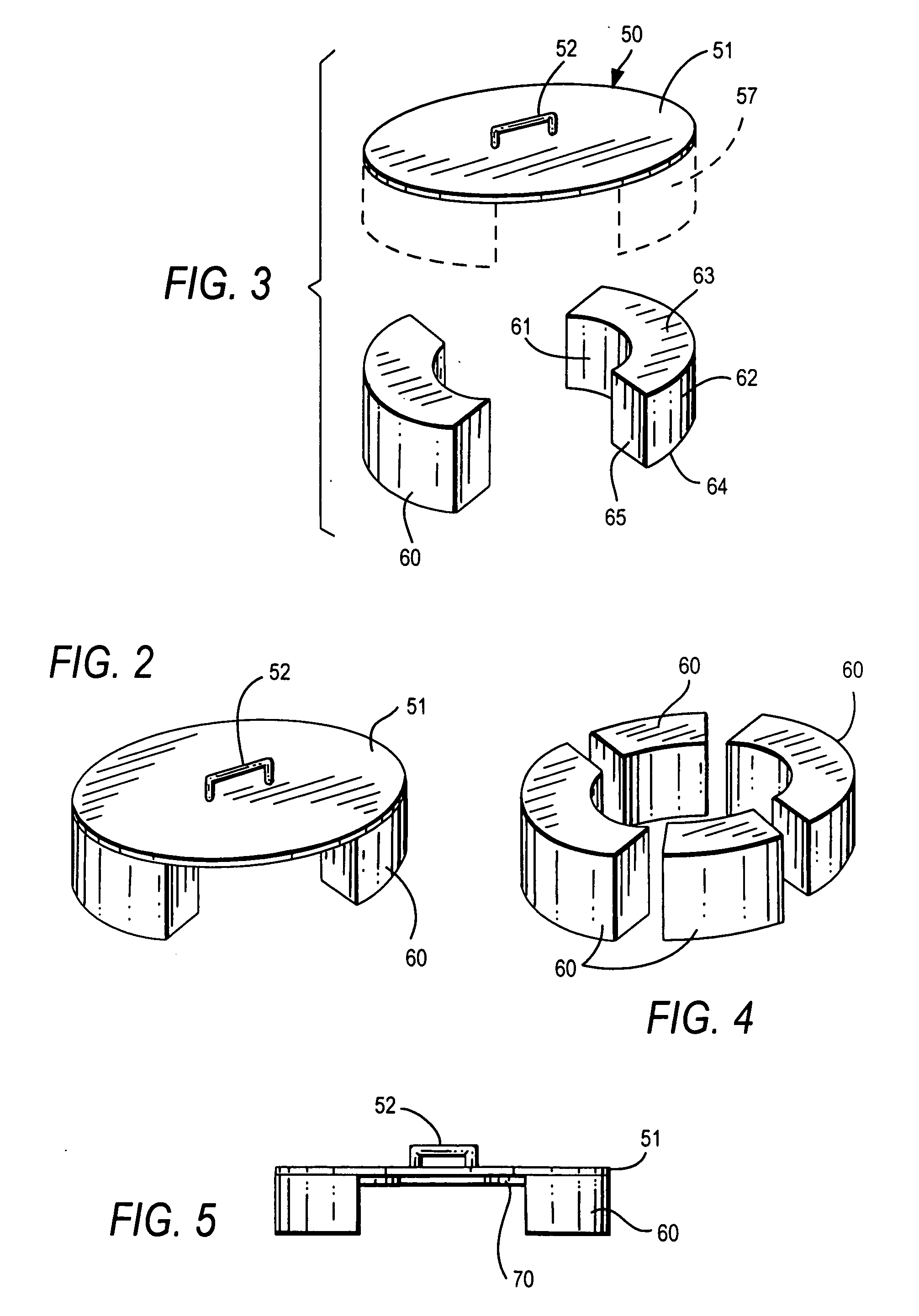
[0024]In a particularly preferred embodiment, the buoyant members are configured so that the surfaces facing the drain pipe generally conform in shape to the exterior contour of the pipe. The buoyant member will thus serve to keep the cover generally centered over the pipe to assure a proper sealing relation when the water has been drained away. The exterior of the drain pipe can be coated with a low-friction industrial paint or polymer to further assure the free relative movement of the assembly.

Problems solved by technology

The water will therefore rise and can inundate the drain sealing mechanism.
The presence of debris carried by the accumulating water can interfere with the proper operation of complex roof drain apparatus known to the prior art.
A further problem can occur when rainwater accumulates on the roof and its effective weight increases to a point where it can overcome the buoyancy of the roof, eventually forcing it into the liquid in the tank.
The valve is again closed when the depth of the water on the roof decreases until it is no longer sufficient to hold the valve open against the buoyancy force of the float.
The above systems for draining water from floating roofs do not overcome the problems of reliability, performance under extreme conditions and secure sealing of the drain opening associated with floating roofs.
That is, unfavourable weather conditions, such as high winds and a significant accumulation of rainwater, may cause the roof to sink.
Another problem to be considered is evaporation losses of liquid product stored in the tank.

Method used


Image

  • Overflow drainage system for floating roof storage tank
  • Overflow drainage system for floating roof storage tank
  • Overflow drainage system for floating roof storage tank

Examples


Embodiment Construction

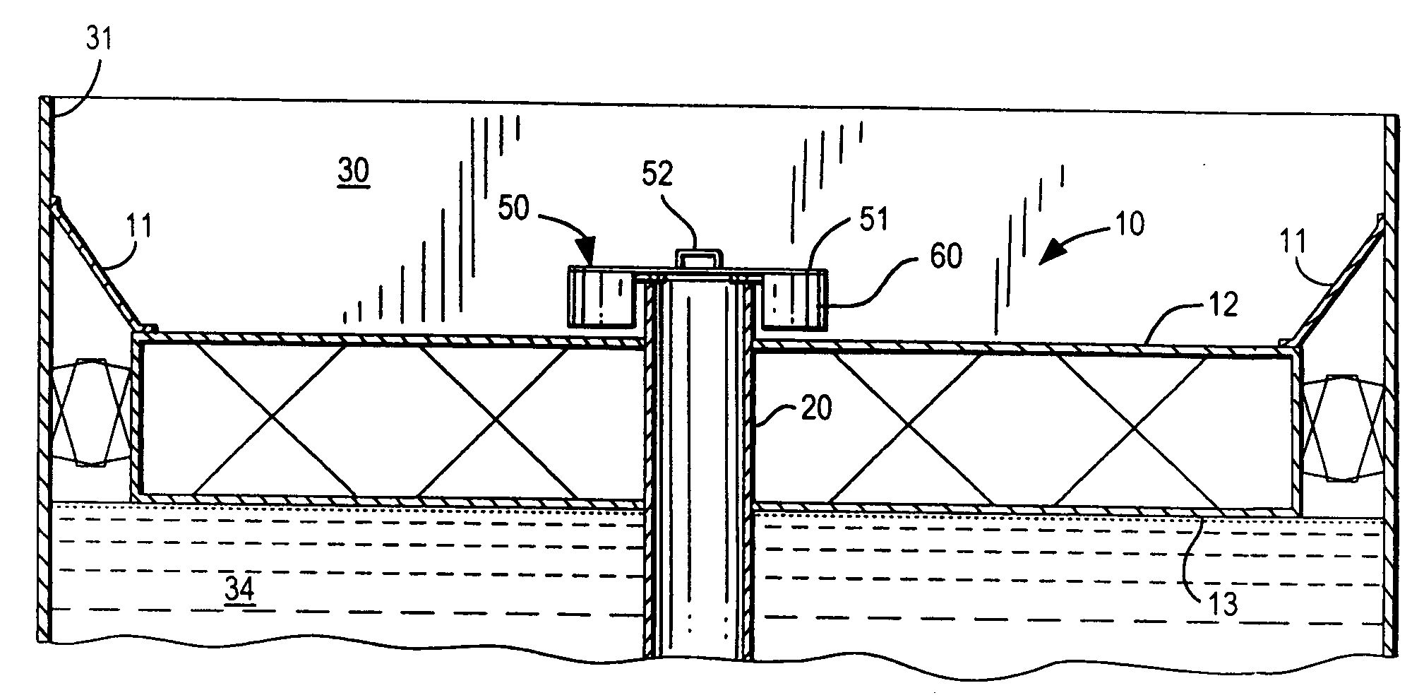
[0035]Referring to FIG. 1, a floating roof 10 is supported by, and floats on a liquid product 34 and sealingly engages the sidewall 31 of tank 30 with a resilient sealing structure 11. The floating roof moves up or down vertically with the level of the liquid product inside the tank. The floating roof 10 has a substantially circular form which conforms to the cross-section of the tank and includes a top deck 12 and a bottom deck 13 joined by an intermediate structure.

[0036]A drain pipe 20 projects vertically from the top deck of the roof 10 and through the two decks 12, 13, to provide a passage for drainage of accumulated water from the top deck 12, into the liquid in the tank.

[0037]Referring to the embodiment shown in FIGS. 1-4, a circular drain cover assembly 50 is mounted on the buoyant pontoons 60 around the drain pipe 20. A flat circular cover plate 51 has a diameter greater than that of the drain pipe 20. A handle or other fitting 52 is secured to the top of the center of the ...


PUM


Abstract

A drain cover assembly for sealing a drain pipe that extends vertically from the top surface of the deck of a floating roof on a liquid storage tank includes a circular cover and at least two buoyant members, or pontoons, secured to the underside of the cover for imparting a buoyant force to raise the cover upon the accumulation of excess water on the deck. The pontoons are spaced apart from each other to allow water to pass between them and into the drainpipe.

Description

FIELD OF THE INVENTION[0001]The present invention relates to a drainage device for use on a floating roof on a storage tank for liquid products.BACKGROUND OF THE INVENTION[0002]Storage tanks for oil and other liquid hydrocarbon products are typically provided with a floating roof. The floating roof moves vertically on the surface of the liquid product to prevent the escape of harmful vapors. A typical floating roof for covering a liquid product in a storage tank includes a deck that substantially conforms to the horizontal cross-sectional shape of the storage tank and has a vertical thickness. The roof is provided with one or more seals extending between the outer periphery of the floating roof and the inner wall of the tank. The roof floats on top of the stored liquid product and rises and falls as the amount of the liquid product increases and decreases. It is known to provide a drain pipe extending vertically through the top surface of deck to drain accumulated water and provide ...

Claims


Application Information

Patent Timeline
Patent Type & Authority Applications(United States)
IPC IPC(8): B65D88/38E04B1/66
CPCB65D88/38
Inventor BEN AFEEF, MOHAMMED A.
Owner SAUDI ARABIAN OIL CO
Learn More