Buck Converter with Internal Ripple Compensation
a buck converter and ripple compensation technology, applied in the field of buck converters, can solve the problems of unstable buck converter b>10/b>, small equivalent series resistance of mlcc, and small ripple voltage generated by the equivalent series resistor esr
- Summary
- Abstract
- Description
- Claims
- Application Information
AI Technical Summary
Benefits of technology
Problems solved by technology
Method used
Image

Examples
first embodiment
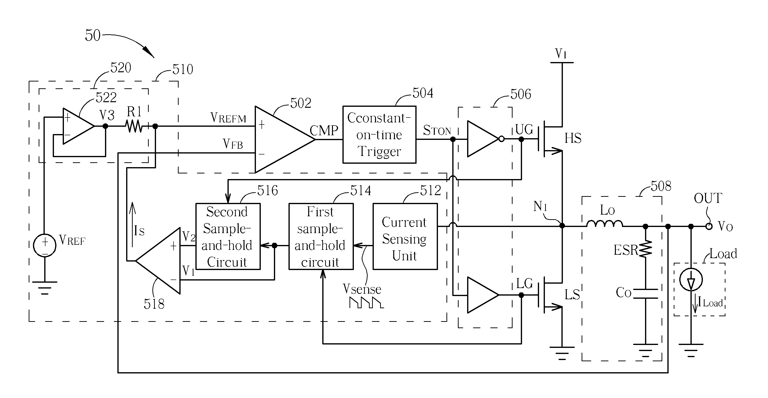
[0028]Please refer to FIG. 5, which is a schematic diagram of a buck converter 50 with internal ripple compensation according to the present invention. The buck converter 50 is utilized for converting an input voltage VI into a stable output voltage VO provided to a load Load. The buck converter 50 includes a comparator 502, a constant-on-time trigger 504, a pre-driver 506, a high side switch HS, a low side switch LS, an output module 508, a ripple compensation circuit 510, and a load Load. The comparator 502 includes a positive input terminal, a negative input terminal, and an output terminal, which is utilized for comparing signals received by the positive input terminal and the negative input terminal (i.e. comparing the compensation signal VREFM with the feedback voltage VFB shown in FIG. 5) in order to generate a comparison result CMP. The constant-on-time trigger 504 is coupled to the output terminal of the comparator 502 for generating a trigger control signal STON according ...
second embodiment
[0035]Please refer to FIG. 8 and FIG. 9. FIG. 8 is a schematic diagram of a buck converter 80 with internal ripple compensation according to the present invention. FIG. 9 is a schematic diagram of signal waveforms of the buck converter 80 shown in FIG. 8 according to an embodiment of the present invention. Please note that the units in the buck converter 80 shown in FIG. 8 with the same designations as those in the buck converter 50 shown in FIG. 5 have similar operations and functions, and further description thereof is omitted for brevity. The interconnections of the units areas shown in FIG. 8. The buck converter 80 includes a comparator 802, a constant-on-time trigger 804, a pre-driver 806, a high side switch HS, a low side switch LS, an output module 808, a ripple compensation circuit 810, and a load Load. The ripple compensation circuit 810 includes a current sensing unit 812, a first sample-and-hold circuit 814, a second sample-and-hold circuit 816, a first voltage-to-current...
PUM
 Abstract
Description
Claims
Application Information
 - R&D Engineer
- R&D Manager
- IP Professional
- Industry Leading Data Capabilities
- Powerful AI technology
- Patent DNA Extraction
Browse by: Latest US Patents, China's latest patents, Technical Efficacy Thesaurus, Application Domain, Technology Topic.
© 2024 PatSnap. All rights reserved.Legal|Privacy policy|Modern Slavery Act Transparency Statement|Sitemap