System and method for synchronous rectifier drive that enables converters to operate in transition and discontinuous mode

a technology of synchronous rectifier drive and discontinuous mode, which is applied in the direction of dc-dc conversion, power conversion system, climate sustainability, etc., can solve the problems of negative current, added complexity and cost to the circuit, energy loss, etc., and achieve the effect of avoiding unneeded transitions of synchronous rectifier switch and protecting against cross-conduction

Active Publication Date: 2010-02-04
TEXAS INSTR INC
View PDF4 Cites 129 Cited by
  • Summary
  • Abstract
  • Description
  • Claims
  • Application Information

AI Technical Summary

Benefits of technology

[0018]According to a feature of the disclosed system and method, undesired transitions of the synchronous rectification switch are avoided by applying blanking intervals during or outside of which control signals or detectors are disabled. In one exemplary embodiment, unwanted control transitions are nullified by starting a blanking timer upon detection of a fast, positive voltage rate of change at the synchronous rectification switch upon primary switch turn on.
[0019]According to another exemplary embodiment, protection against cross-conduction between the synchronous rectifier switch and the primary switch is provided by detecting when the primary switch turns on. The detection of primary switch turn-on causes the synchronous rectifier to be turned off. Primary switch turn-on is detected using any one of a number of different techniques, for example, by using a small capacitance and a comparator to detect the fast negative voltage transition during turn-on at the drain of the primary switch. The comparator output is used to turn off, or ensure a turn-off state for the synchronous rectifier on the secondary side of the transformer.
[0020]Another exemplary embodiment for detection of primary switch turn-on provides a signal transformer coupled to the primary switch that is used to determine when the primary switch turns on to cause the synchronous rectifier to turn off. The signal transformer can be a pulse transformer coupled to a gate or a drain of the primary switch through a capacitor to provide a pulse that may be used as a logic signal to turn off the synchronous rectifier when the primary switch turns on. A signal transformer may also be used between a primary side of the power transformer and the primary switch to provide a logic pulse to a synchronous rectifier control to turn off the synchronous rectifier when the primary switch turns on. According to another exemplary embodiment, protection against cross-conduction is provided by limiting the on-time of the synchronous rectification switch with a timer. At the expiration of the timer time interval, the synchronous rectification switch is turned off or a turn-off state is ensured or maintained.

Problems solved by technology

However, operating switches Q2 and Q3 in such a configuration presents difficulties for operation of the flyback converter in circuit 120.
One drawback with providing complementary signals to drive switches Q2 and Q3 is that current Is can become negative.
In this circumstance, a substantial amount of energy is circulated between the input and output of flyback converter 120, resulting in energy losses.
However, the use of a magnetic component to sense current adds complexity and cost to the circuit, so that such a sensing technique is not commercially attractive.
However, an appropriate switching control for switch Q3 using this technique calls for the use of very high speed, high sensitivity comparators, that are difficult to implement and are prone to faulty operation in the presence of noise, such as typically exists in a flyback converter environment.

Method used


Image

  • System and method for synchronous rectifier drive that enables converters to operate in transition and discontinuous mode
  • System and method for synchronous rectifier drive that enables converters to operate in transition and discontinuous mode
  • System and method for synchronous rectifier drive that enables converters to operate in transition and discontinuous mode

Examples


Embodiment Construction

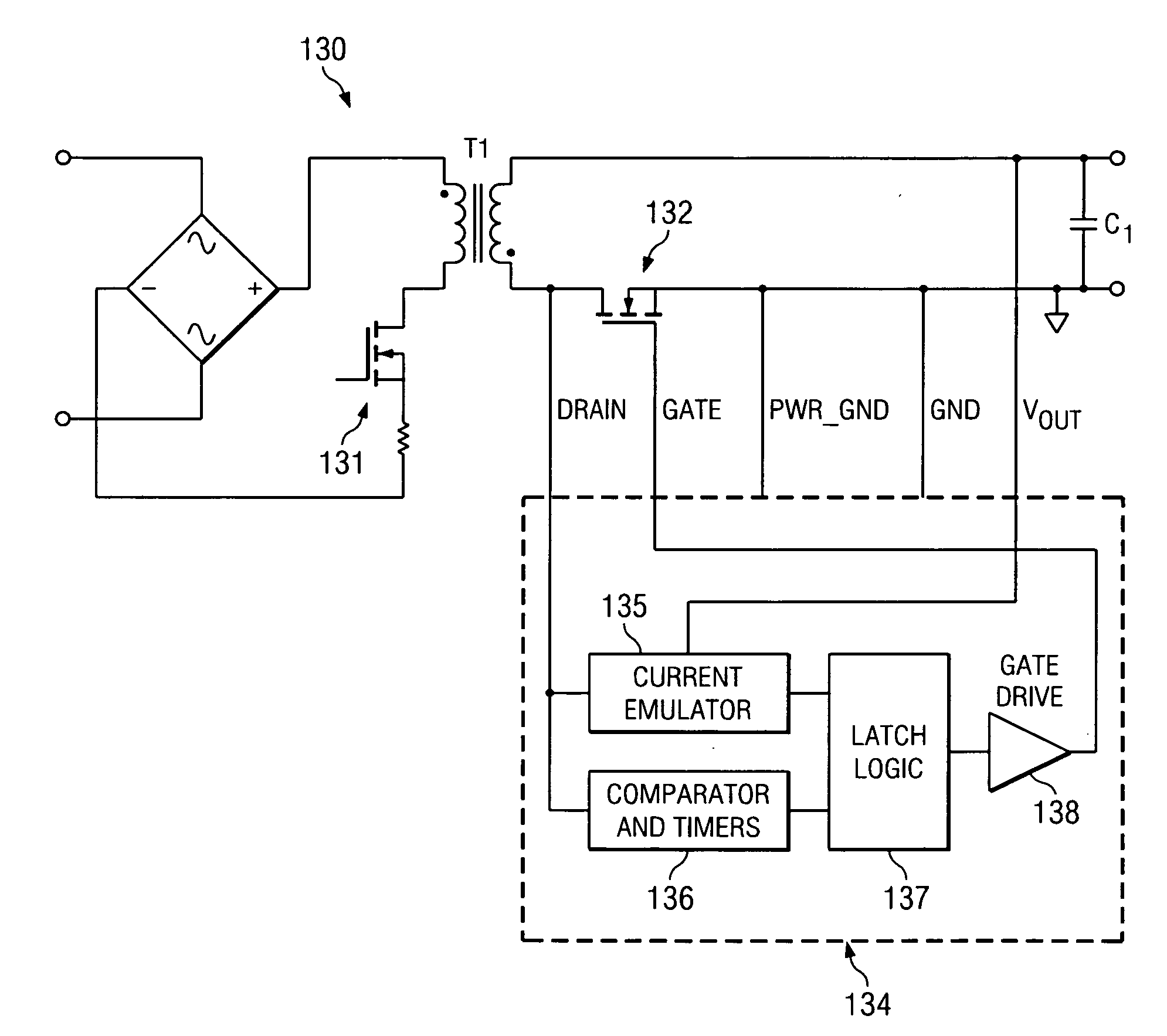
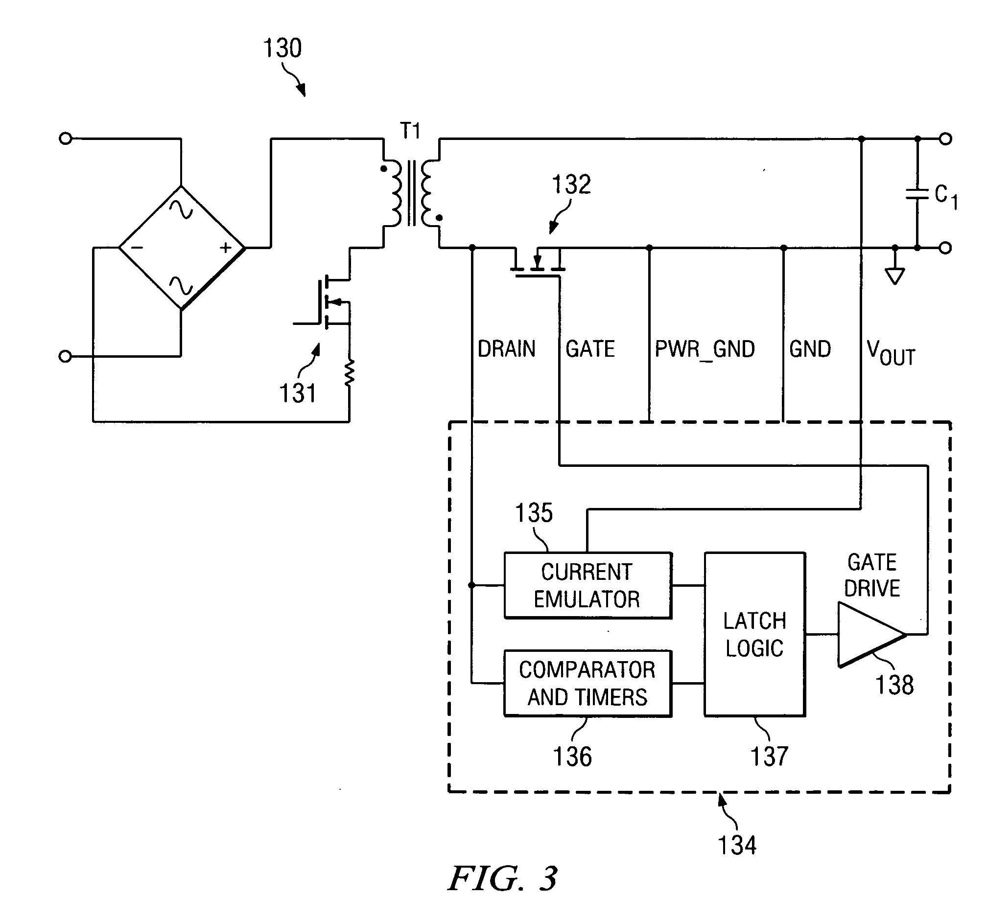
[0034]Referring now to FIG. 3, a block diagram of a flyback converter 130 is illustrated in accordance with an exemplary embodiment of the disclosed system and method. Flyback converter 130 includes a synchronous rectifier in the form of a MOSFET switch 132. Switch 132 is connected between a secondary side of a transformer T1 and a ground reference potential. Switch 132 is operated as a synchronous rectifier based on signals supplied by a controller 134. Controller 134 senses the drain voltage on switch 132, as well as output voltage Vout, and derives a gate control signal applied to the gate of switch 132 to produce synchronous rectification.

[0035]Controller 134 includes a current emulator 135 for emulating current in transformer T1. Current emulator 135 senses output voltage Vout and the drain voltage of switch 132 to construct a signal representing the current in the primary side of transformer T1 while primary side switch 131 is on. The signal representing primary side transform...


PUM


Abstract

A synchronous rectifier is switched in accordance with a primary switch transition and a reference signal representing current in a current storage device to which the synchronous rectifier is coupled. A current emulator provides a signal representing current in the current storage device as a volt-second product so that current stored in the current storage device while the primary switch is on is discharged by the synchronous rectifier. The use of a current emulator provides an inexpensive solution for controlling synchronous rectifier transitions without resorting to more expensive current sensing solutions that are commercially impracticable. Blanking intervals are provided for avoiding false transitions of the synchronous rectifier when the primary switch turns on and after the synchronous rectifier turns off. The disclosed system and method can be applied to flyback converters for a synchronous rectifier on the secondary side of a transformer, or the inductor of buck converters.

Description

CROSS REFERENCE TO RELATED APPLICATIONS[0001]N / ASTATEMENT REGARDING FEDERALLY SPONSORED RESEARCH OR DEVELOPMENT[0002]N / ABACKGROUND OF THE INVENTION[0003]1. Field of the Invention[0004]The present disclosure relates generally to a system and method for a synchronous rectifier drive, and relates more particularly to a low-cost synchronous rectifier drive for use in power converters, particularly flyback power converters operating in transition and discontinuous mode.[0005]2. Description of Related Art[0006]Synchronous rectifiers are typically implemented as a replacement for a diode operating alone to emulate diode operation with improvements in efficiency. Typically, a transistor switch with a low forward conducting resistance and high blocking impedance takes the place of a diode. The switch is turned off to block conduction in one direction, and switched on with current flowing in another direction to provide a low forward voltage drop for conducting current. The switching events a...

Claims


Application Information

Patent Timeline
Patent Type & Authority Applications(United States)
IPC IPC(8): H02M3/335
CPCY02B70/1475H02M3/33592Y02B70/10
Inventor COHEN, ISAAC
Owner TEXAS INSTR INC
Why Eureka
Try Eureka