An integrated dual-output grid-to-vehicle (G2V) and vehicle-to-grid (V2G) onboard charger for plug-in electric vehicles

a plug-in electric vehicle and charger technology, applied in the direction of battery/fuel cell control arrangement, process and machine control, instruments, etc., can solve the problems of reducing charging efficiency, low-power onboard chargers, and unidirectionality of commercially available and upcoming onboard l1 and l2 chargers, so as to increase the power density of converters and reduce the size of converters

Active Publication Date: 2016-01-21
UNIV OF MARYLAND
View PDF16 Cites 124 Cited by
  • Summary
  • Abstract
  • Description
  • Claims
  • Application Information

AI Technical Summary

Benefits of technology

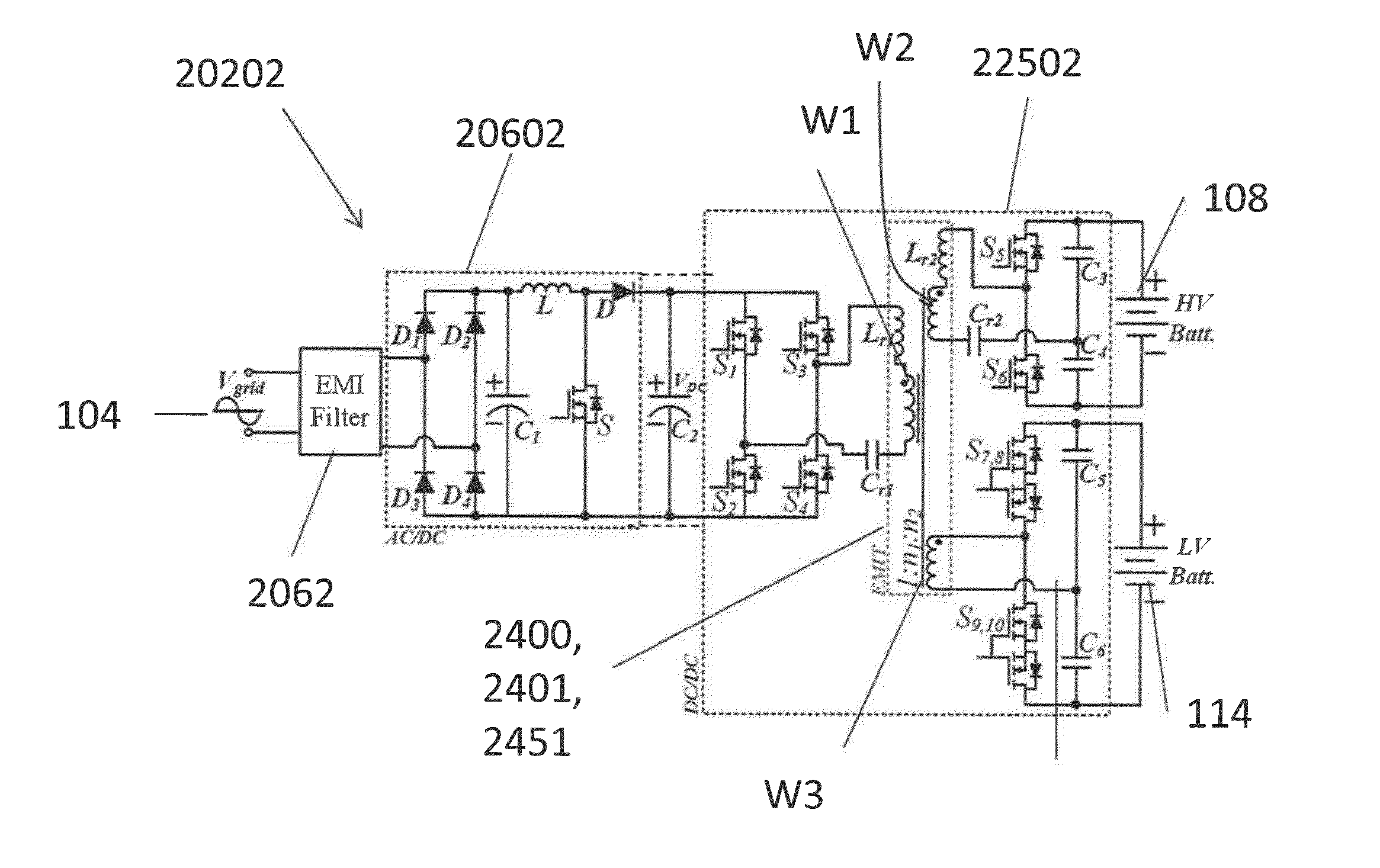
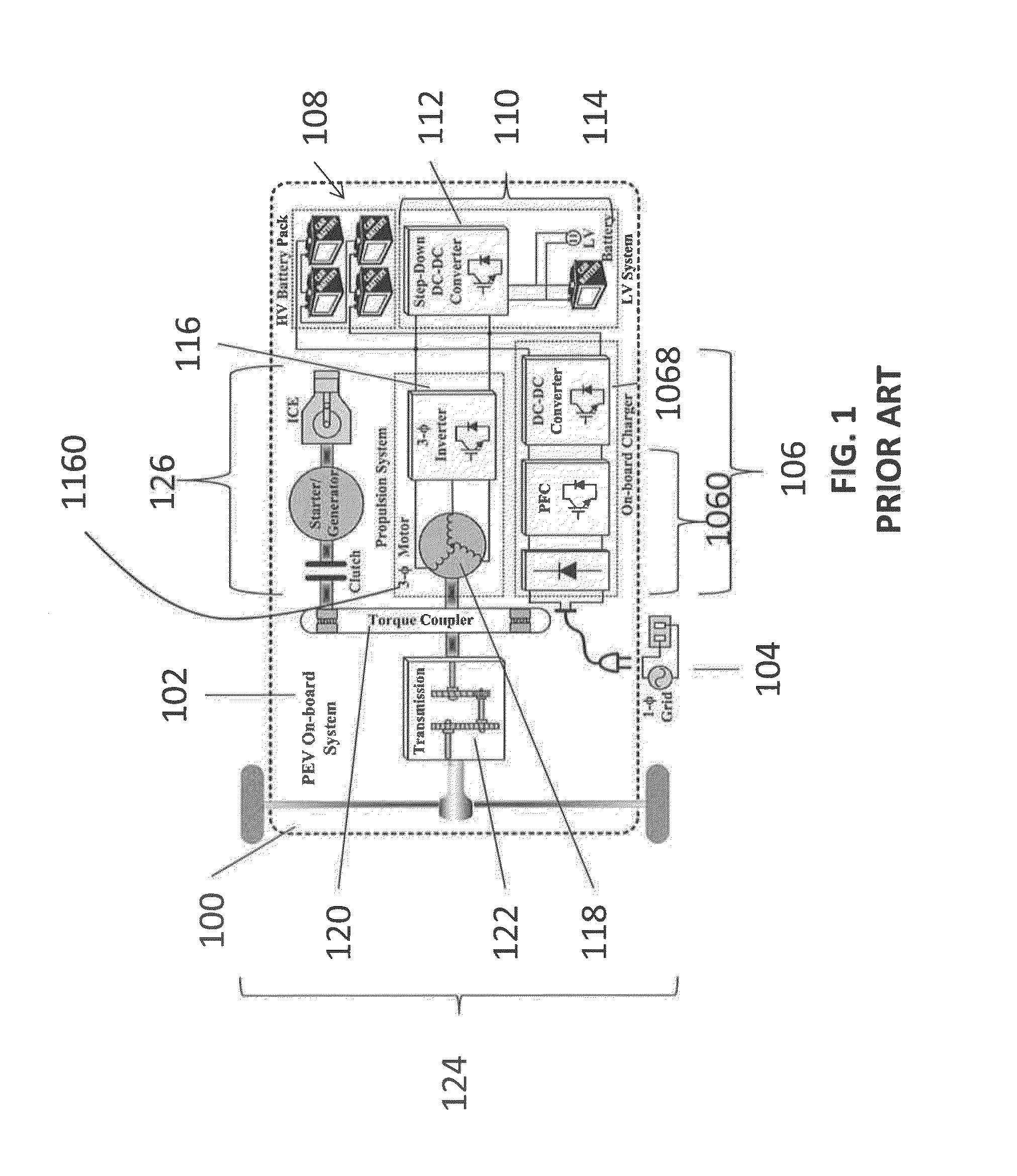
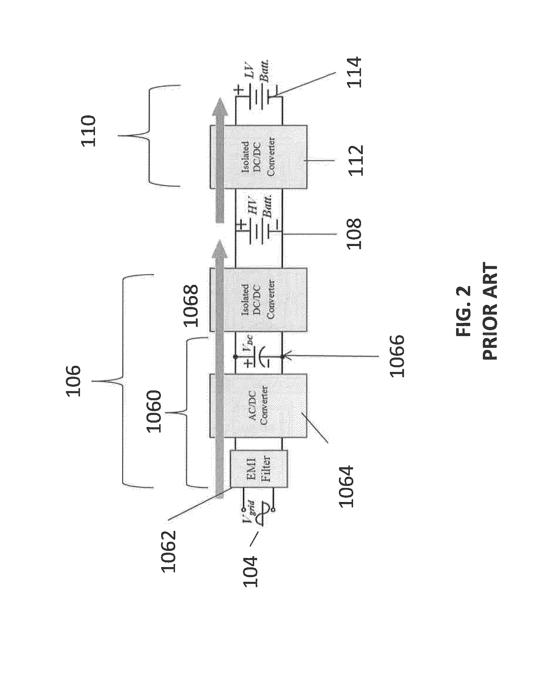
[0018]The present disclosure relates to an integrated and isolated onboard charger for plug-in electric vehicles that includes an ac-dc converter and a dual-output dc-dc resonant converter, for both HV traction batteries and LV loads. In addition, the integrated and isolated onboard charger may be configured as unidirectional or bidirectional, and is capable of delivering power from HV fraction batteries to the grid for vehicle-to-grid (V2G) applications. To increase the power density of the converter, the dual-output DC-DC resonant converter may combine magnetic components of resonant networks into a single three-winding electromagnetically integr

Problems solved by technology

A majority of the commercially available and upcoming onboard L1 and L2 chargers are unidirectional.
However, such topologies require more transistors and diodes, and integrating a high-power dc-dc converter with a low-power onboard charger might reduce the charging efficiency.
In addition, some PEVs might not be equipped with a bidirectional converter between HV battery pack and propulsion inverter.
Other researchers have studied the integration of isolated onboard chargers using either phase-shift active-b

Method used


Image

  • An integrated dual-output grid-to-vehicle (G2V) and vehicle-to-grid (V2G) onboard charger for plug-in electric vehicles
  • An integrated dual-output grid-to-vehicle (G2V) and vehicle-to-grid (V2G) onboard charger for plug-in electric vehicles
  • An integrated dual-output grid-to-vehicle (G2V) and vehicle-to-grid (V2G) onboard charger for plug-in electric vehicles

Examples


Embodiment Construction

[0078]For the purposes of promoting an understanding of the principles of the present disclosure, reference will now be made to the exemplary embodiments illustrated in the drawings, and specific language will be used to describe the same. It will nevertheless be understood that no limitation of the scope of the present disclosure is thereby intended. Any alterations and further modifications of the inventive features illustrated herein, and any additional applications of the principles of the present disclosure as illustrated herein, which would occur to one skilled in the relevant art and having possession of this disclosure, are to be considered within the scope of the present disclosure.

[0079]The word “exemplary” is used herein to mean “serving as an example, instance, or illustration.” Any embodiment described herein as “exemplary” is not necessarily to be construed as preferred or advantageous over other embodiments.

[0080]It is to be understood that the method steps described ...


PUM


Abstract

An integrated and isolated onboard charger for plug-in electric vehicles, includes an ac-dc converter and a dual-output dc-dc resonant converter, for both HV traction batteries and LV loads. In addition, the integrated and isolated onboard charger may be configured as unidirectional or bidirectional, and is capable of delivering power from HV traction batteries to the grid for vehicle-to-grid (V2G) applications. To increase the power density of the converter, the dual-output DC-DC resonant converter may combine magnetic components of resonant networks into a single three-winding electromagnetically integrated transformer (EMIT). The resonant converter may be configured as a half-bridge topology with split capacitors as the resonant network components to further reduce the size of converter. The integrated charger may be configured for various operating modes, including grid to vehicle (G2V), vehicle to grid (V2G) and high voltage to low voltage, HV-to-LV (H2L) charging.

Description

CROSS-REFERENCE TO RELATED APPLICATIONS[0001]This application claims priority to, and benefit of, U.S. Provisional Patent Application No. 62 / 011,649 filed on Jun. 13, 2014, entitled “INTEGRATED POWER ELECTRONIC CHARGER FOR PLUG-IN ELECTRIC VEHICLES”, by Alireza Khaligh, the entire contents of which is incorporated by reference herein.BACKGROUND[0002]1. Technical Field[0003]The present disclosure relates to plug-in hybrid electric vehicles (PHEVs) and electric vehicles (EVs) and more particularly to on-board chargers for such vehicles.[0004]2. Description of Related Art[0005]Plug-in hybrid electric vehicles (PHEVs) and electric vehicles (EVs), cumulatively called plug-in electric vehicles (PEVs), need to be equipped with an on-board charger. Such on-board chargers are generally categorized as onboard level-1 (L1) grid-to-vehicle (G2V) chargers and level-2 (L2) grid-to-vehicle (G2V) chargers to charge the high-voltage (HV) traction batteries in plug-in electric vehicles (PEVs).[0006]F...

Claims


Application Information

Patent Timeline
IPC IPC(8): B60L11/18H01F27/24H01F27/28H02M1/42H02M3/335
CPCB60L11/1812H02M1/4208H01F27/2823H01F27/24H02M3/33592H01F3/14H01F27/38H01F38/08B60L2210/30B60L2210/40Y02T10/92Y02T10/7072Y02T90/14Y04S10/126B60L53/14B60L53/22B60L55/00B60L58/20H02M1/4258Y02E60/00Y02T10/70Y02T10/72H02M1/0058H02M1/008H02M1/007H02M3/1586H02M3/33561H02M3/33584B60L2210/10
Inventor KHALIGH, ALIREZATANG, YICHAO
Owner UNIV OF MARYLAND
Why Eureka
Try Eureka