Remotely controllable photo booth with interactive slide show and live video displays

a photo booth and slide show technology, applied in closed circuit television systems, television systems, instruments, etc., can solve the problems of limiting the use of many members of the purchasing public, the inability of photo booth innovations to match the rapid pace of electronics industry development, and the limited range of photo booth innovations

Inactive Publication Date: 2011-09-29
WEISBERG ALLEN
View PDF4 Cites 92 Cited by
  • Summary
  • Abstract
  • Description
  • Claims
  • Application Information

AI Technical Summary

Benefits of technology

[0027]A device of the current invention is an advanced photo booth which offers both the owner and the patron more options and possibilities than have previously been available. The device herein features at least an external monitor, at least one capturing means for recording an image of a user, and a payment means for permitting the user to purchase a product of the system. The present invention uses at least one camera, preferably an exterior camera, and face tracking technology to capture the image of persons walking past, and to rapidly manipulate the image on screen to attract the person's attention, and alert the potential customer to the various different photo options that are available in the booth. By the term photo booth is meant a means for capturing an image of a person, a means for displaying the image, and a means for such person to purchase the image. The booth may be an external arrangement or it may include a private area where a user may have one or more

Problems solved by technology

Innovative changes in photo booths have not matched the rapid pace of developments within the electronics industry.
U.S. Pat. No. 6,619,860 to Simon discloses the use of a monitor to attract patrons walking past the booth; however, it is extremely limited in that it merely comprises

Method used


Image

  • Remotely controllable photo booth with interactive slide show and live video displays
  • Remotely controllable photo booth with interactive slide show and live video displays
  • Remotely controllable photo booth with interactive slide show and live video displays

Examples


Embodiment Construction

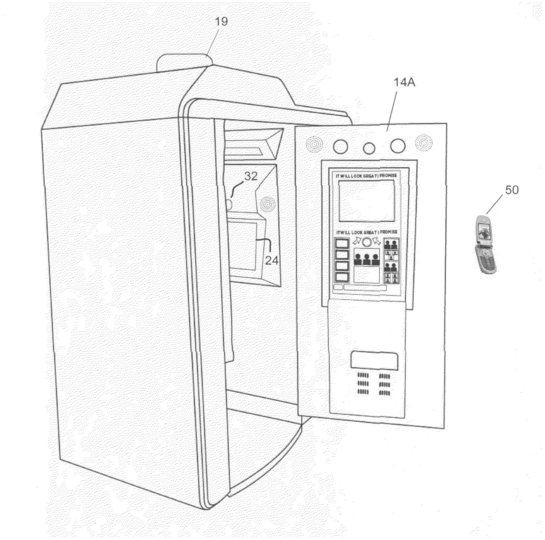
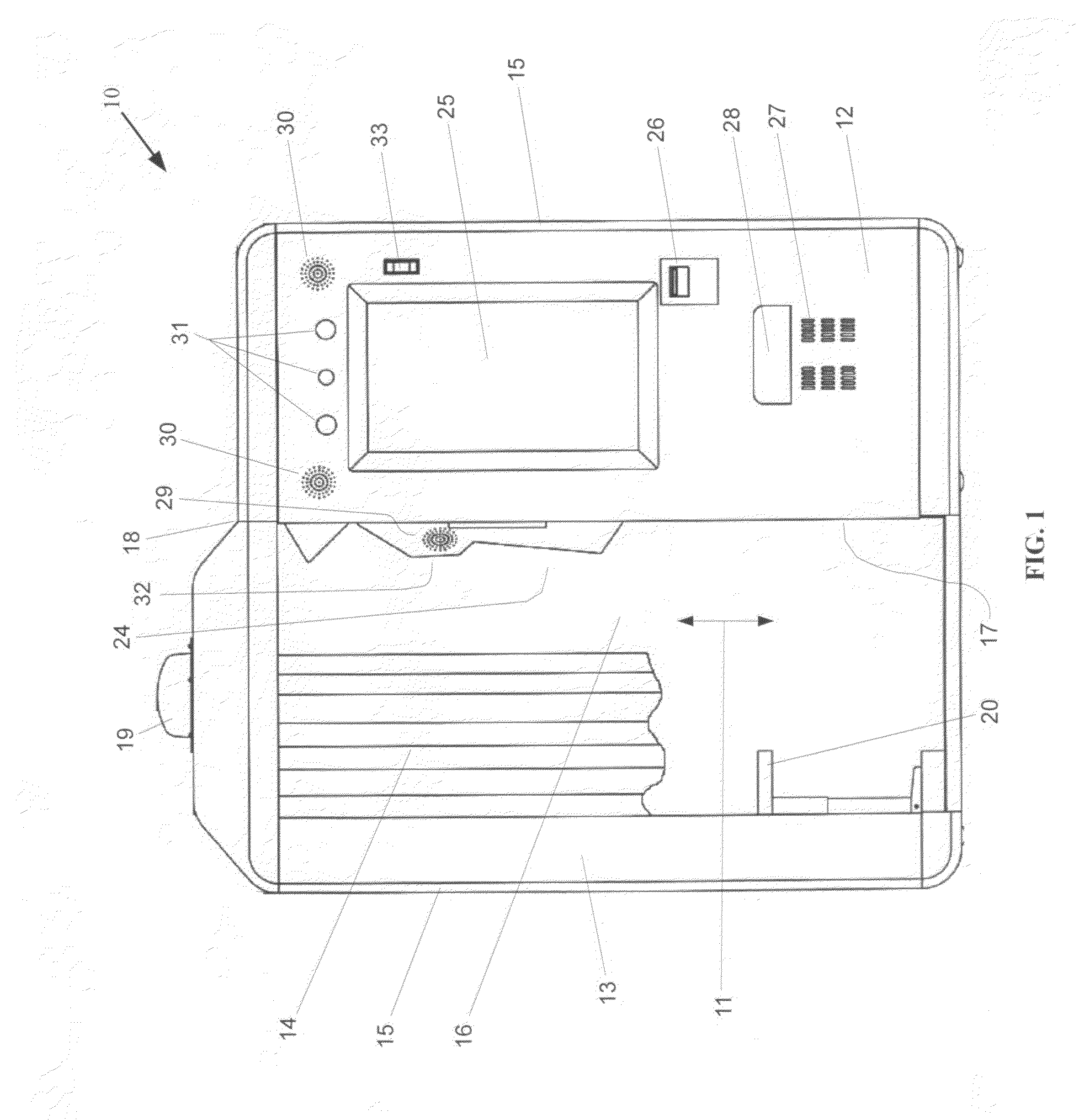
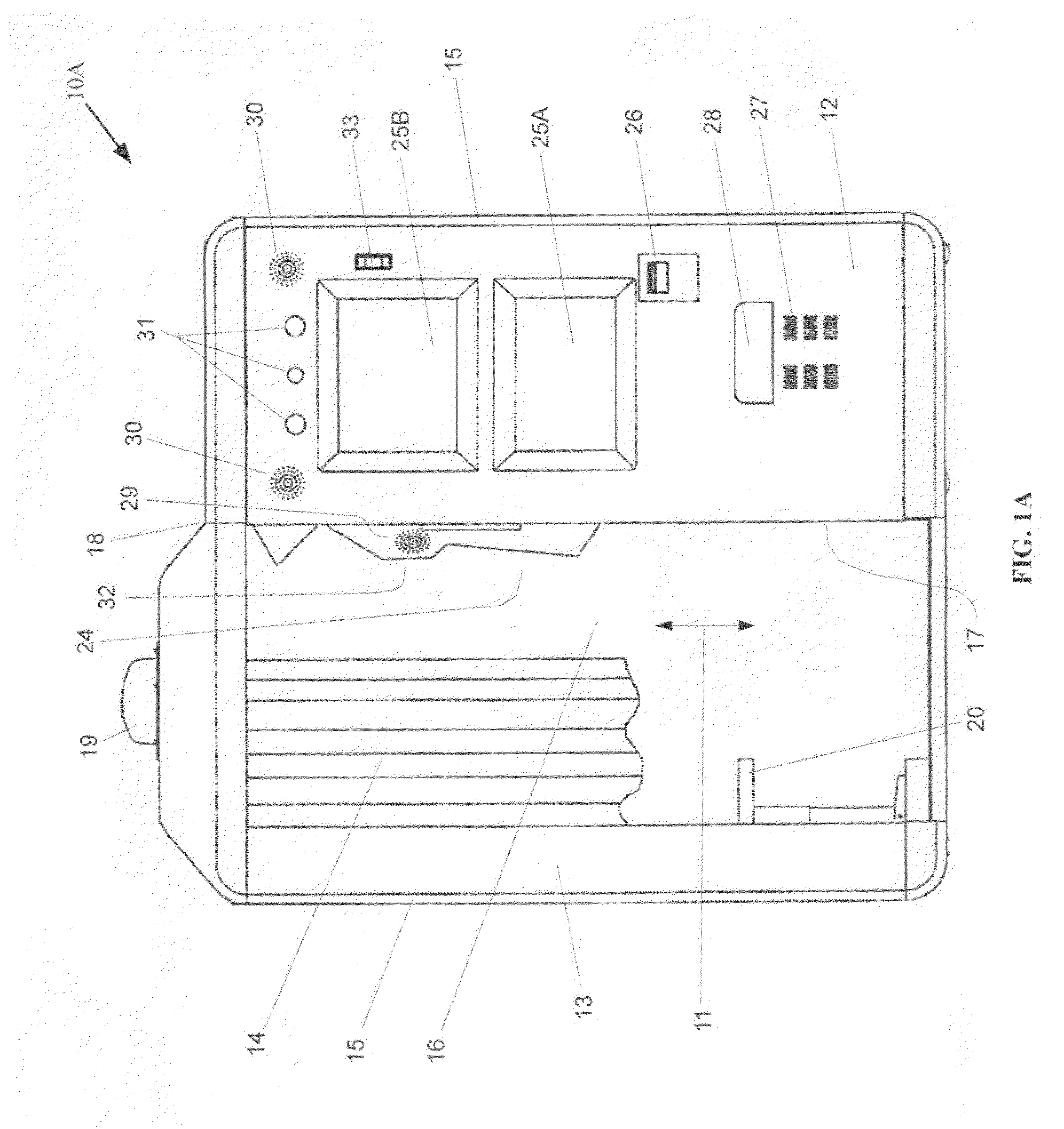
[0063]The photo booth of the current invention, as seen in a first embodiment in FIG. 1, may have an enclosure forming an interior, and having exterior surfaces. The photo booth 10 may be comprised of a front main wall 13, side walls 15, a rear wall 16, and a roof wall 18. There may also be a dividing wall 17 between the side walls 30 to serve to divide the booth and create the booth interior 11, which may have a bench 20 therein, and an adjacent compartment for storing the electronic and other components of the photo booth. The adjacent compartment may be enclosed by a hinged front access panel 12, which may be secured using a door latch and lock 35. The separation between the end of the front wall 13 and the dividing wall 17 is usable as an opening into the interior 11, and may have a traditional curtain 14 (FIG. 1) attached thereto, or a solid door 14A (FIG. 2), which may afford greater privacy for booth users and may also improve the lighting for the digital photographic experie...


PUM


Abstract

An advanced photo booth comprises a camera, a kiosk printer; and attraction means for inducing patronage of passers-by. The attraction means comprises: a camera and a touch screen for capturing and displaying passerby images; and interactive communication with passers-by. Interactive communication may include personalized greetings made possible through facial recognition techniques that compare a presently captured passerby image with previous passerby and patron images stored in a memory. Digital image processing techniques automatically permit proper tilting of a head in the display screen, regardless of a head position in captured passerby images. The attraction means also comprises a second exterior display screen usable for advertising and CATV broadcasts. The passerby touch screen or a touch screen display within the enclosure permits customization of digital images, including: face replacement, hair replacement, and background selection; and also permits previewing of customized images. Remote control capabilities enhance the flexibility of booth operations.

Description

CROSS REFERENCES TO RELATED APPLICATIONS[0001]This application claims priority on U.S. Provisional Application Ser. No. 61 / 339,662, filed on Mar. 5, 2010, the disclosures of which are incorporated herein by reference.FIELD OF THE INVENTION[0002]The present invention relates to improvements in automated photography booths, and more particularly to systems, methods, and apparatus which expand and improve the functionality and variety of products available from such booths, and more particularly to apparatus and systems which provide an automated kiosk approach to attracting customers.BACKGROUND OF THE INVENTION[0003]The vending business within the United States is a growing and evolving source of revenue. In 2008, automatic vending machine revenue was a billion dollar industry, and had experienced an increase over the estimated 2007 sales. Although the lion's share of the market is occupied by machines which sell snacks and candies, and the, complementary vended product of soft drinks...

Claims


Application Information

Patent Timeline
IPC IPC(8): H04N7/18
CPCG03B17/53H04N7/183H04N1/00132
Inventor WEISBERG, ALLEN
Owner WEISBERG ALLEN
Why Eureka
Try Eureka