Music amplifier/ mixer

a technology of amplifier and mixer, which is applied in the direction of digitised analogue information signals for electronic editing, television systems, and scanning details of television systems, etc., can solve the problems of difficulty in evaluating sound quality, and inability to monitor other input sources. , to achieve the effect of a lot of convenience and flexibility for the operator

Inactive Publication Date: 2011-09-29
SU DAVID
View PDF4 Cites 2 Cited by
  • Summary
  • Abstract
  • Description
  • Claims
  • Application Information

AI Technical Summary

Benefits of technology

[0008]With the development of analog and digital signal processing technique, audio and video signals are able to be indicated and processed in many manners. This provides a lot of capability to monitor and process the signals. In the present invention, besides listen to the sound, the mixer enable the operator to “see” the sound. The audio signals are described graphically and numerically therefore the operator is able to monitor the property of the signals which is much more accurate and reliable. The output of the mixer of the present invention is also able to be recorded in different formats to provide a lot of convenience and flexibility to the operator.
[0009]An object of the present invention is to provide a music mixer which input and output can be monitored visually.
[0013]Another object of the present invention is to provide a music mixer which output is able to be recorded.
[0014]Another object of the present invention is to provide a music mixer which output is able to be recorded in different formats.

Problems solved by technology

For people without enough training, it is very difficult for them to evaluate the quality of the sound, and to make suitable adjustment of the mixer to improve the sound effects.
In addition, when the output of a mixer is occupied by one input source, operator cannot monitor other input source at the same time.
Although some mixer use LED to indicate the volume of the output signal at different frequencies, there is not accurate and reliable way for the operator to monitor the input and output of the mixer.
Also, the output signal of current using music mixers can only be monitored lively which means there is no playback function.
In addition, the output signals which are recorded by the external equipments are analog signals which is inconvenient to store and process.

Method used


Image

  • Music amplifier/ mixer
  • Music amplifier/ mixer
  • Music amplifier/ mixer

Examples


Embodiment Construction

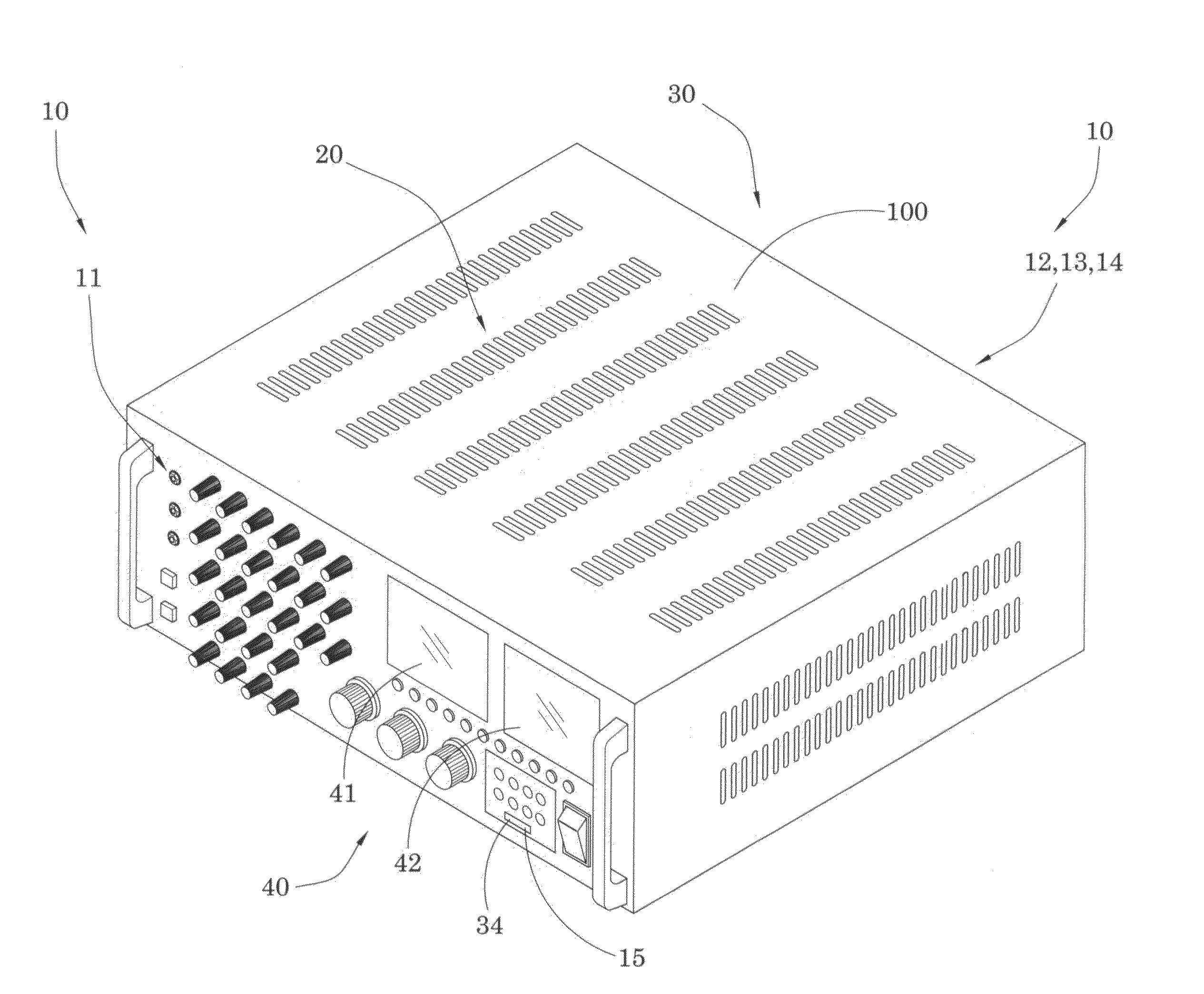
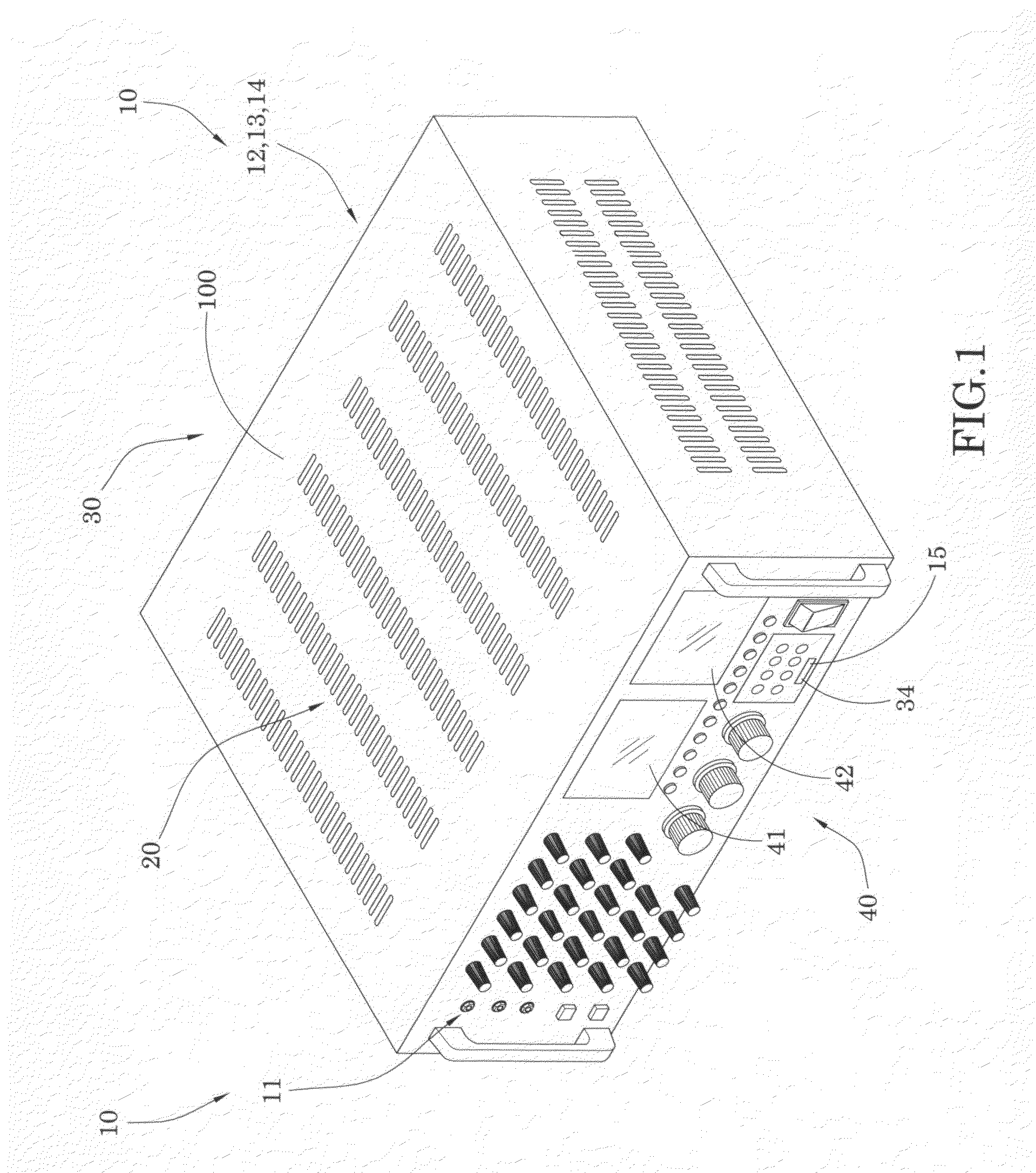
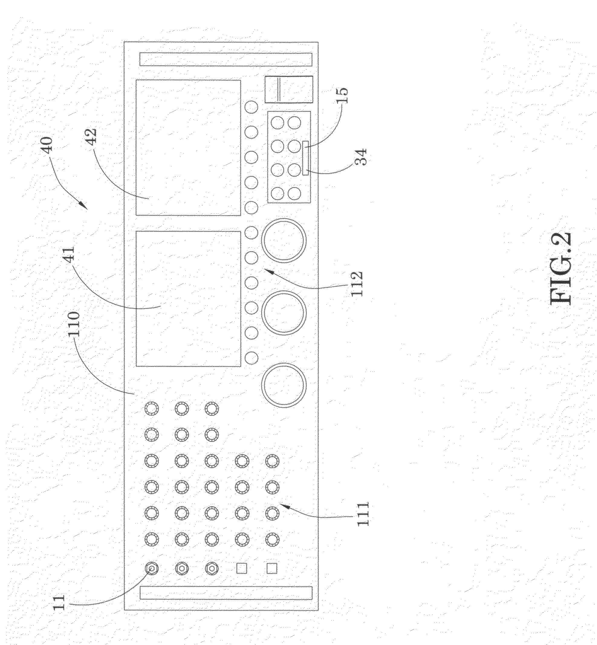
[0031]Referring to FIGS. 1 to 3 of the drawings, in a preferred embodiment of the present invention, a music mixer comprises an input component 10 having a plurality of individual input terminals 10′, an audio / video processing component 20, and an output component 30.

[0032]The individual input terminals 10′ further comprises one or more microphone input channels 11 for collecting vocal signals, one or more auxiliary (AUX) input channel 12 for receiving external audio sources, one or more video input channels 13 for inputting video signals which are communicatively connected with a plurality of audio / video input signals including.

[0033]In a preferred embodiment of the present invention, the individual input terminals 10′ also comprise digital signal input sources which include a USB port 14 to receive data from external electronic devices such as PC, and a data storage reader 15 to read data from a data storage. Preferably, the storage reader is a SD card reader, and the data storage...


PUM


Abstract

A music mixer has an input component comprising a plurality of input sources to provide audio / video input signals; an audio / video processing component selectively receiving the input signals from the input component, processing and mixing the audio / video input signals to generate audio / video output signals and control information; and an output component outputting the audio / video output, wherein the output component further provides visual image of the video output signals and the control information.

Description

BACKGROUND OF THE PRESENT INVENTION[0001]1. Field of Invention[0002]The present invention relates to a audio mixer, and more particularly to a music mixer with amplifier and output monitor.[0003]2. Description of Related Arts[0004]A music mixer is also called audio mixer which is an electrical device to process and combine multiple audio inputs together to form an output audio signal. This signal will be transferred to output devices such as loud speakers for producing audible sound. The output signal includes analog signal and digital signal. Often time, the voltage level of the output signal is low and needs an amplifier to increase the signal power to drive the output devices.[0005]Most music mixers have multiple audio input channels and many functions to process the audio inputs. For example, the user needs to select different input channels, adjust timbre, routing, and level of the input, and sometimes needs to monitor the video output of sources such as DVD. To handle all thes...

Claims


Application Information

Patent Timeline
Patent Type & Authority Applications(United States)
IPC IPC(8): H04N3/27H04B1/00
CPCG11B27/038
Inventor SU, DAVID
Owner SU DAVID
Why Eureka
Try Eureka