Light source unit and projector

a technology of light source unit and projector, which is applied in the direction of lighting and heating apparatus, semiconductor devices of light sources, instruments, etc., can solve the problems of reducing the utilization efficiency of light emitted from the laser emitter, generating luminance saturation of luminescent material or failure of scorching, etc., to prevent luminance saturation, increase the utilization efficiency of excitation light, and free

Active Publication Date: 2011-09-29
CASIO COMPUTER CO LTD
View PDF5 Cites 38 Cited by
  • Summary
  • Abstract
  • Description
  • Claims
  • Application Information

AI Technical Summary

Benefits of technology

[0012]According to the aspects of the invention, there can be provided the light source unit which can prevent the luminance saturation of the luminescent material or the failure thereof which is attributed to scorching and increase the utilization efficiency of excitation light so that the luminescent material becomes luminous uniformly, and the projector comprising this light source unit to thereby enable a projection which is free from luminance non-uniformity and remains stable for a long period of time.

Problems solved by technology

However, when a laser emitter is used as an excitation light source, in the event that the power of a laser beam emitted from the laser emitter is increased, there has been caused a fear that the luminance saturation of the luminescent material or a failure thereof attributed to scorching is generated.
On the other hand, when a laser beam is shone onto the luminescent material layer while being diffused to weaken the power per unit area of the laser beam with the power of the laser bean being increased, the area illuminated by the laser beam gets wider than the area of the portion of the luminescent material layer that is to be illuminated by the laser beam, whereby the laser beam is shone onto positions which lie out of the luminescent material layer, leading to a problem that the utilization efficiency of light emitted from the laser emitter is decreased.

Method used


Image

  • Light source unit and projector
  • Light source unit and projector
  • Light source unit and projector

Examples


Embodiment Construction

[0021]Hereinafter, a preferred mode for carrying out the invention will be described by use of the accompanying drawings. Although various limitations which are technically preferable in carrying out the invention are imposed on an embodiment which will be described below, the scope of the invention is not limited in any way to the following description and illustrated examples.

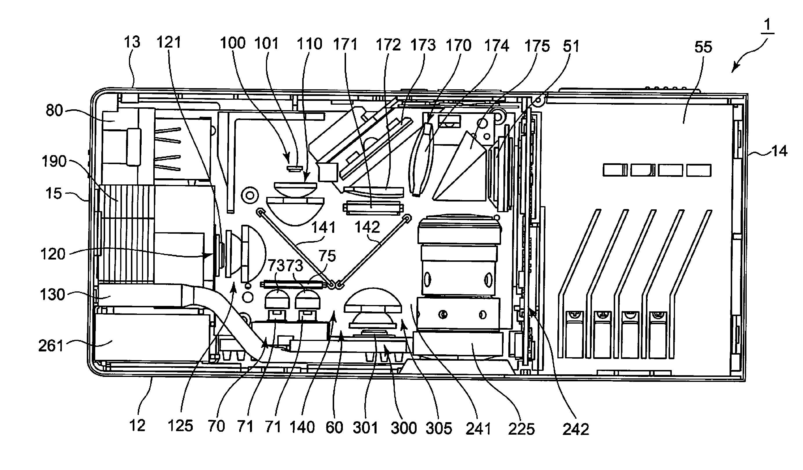
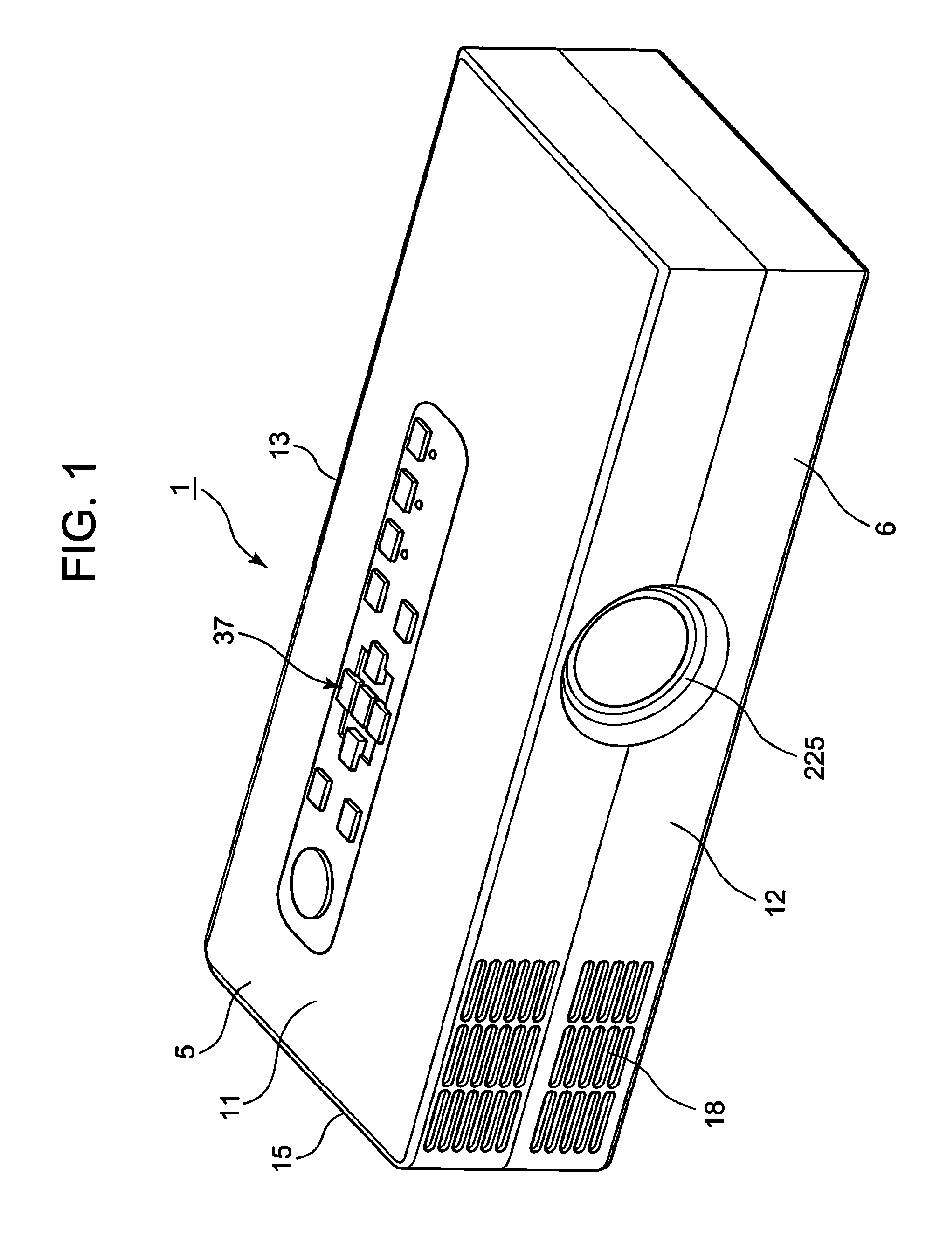
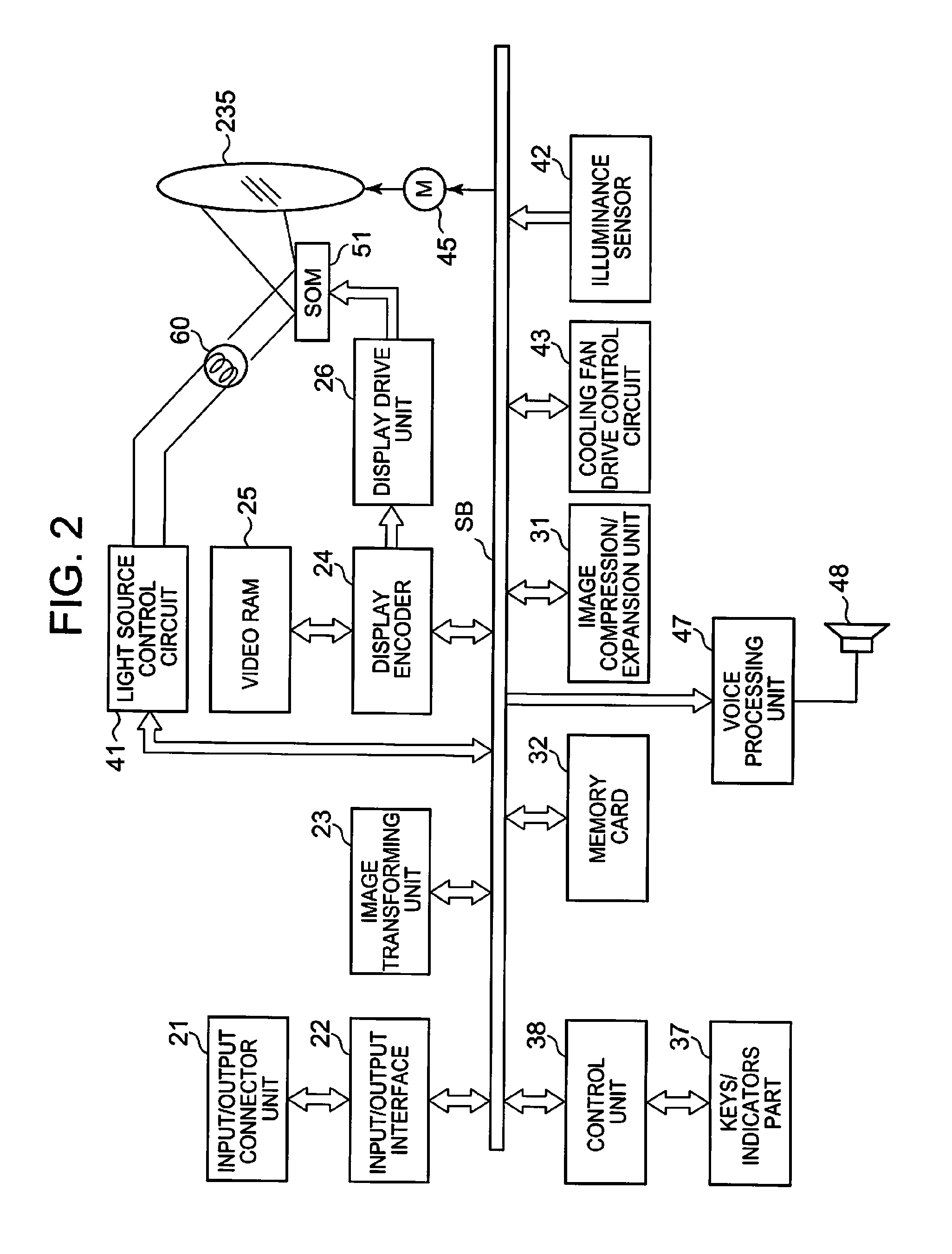
[0022]A projector 1 according to the invention includes a light source unit 60, a display device 51, a projection-side optical system, a light guiding optical system 170 for guiding light from the light source unit 60 to the display device 51 and for aligning a optical axis of a projection light which is generated in the display device 51 with a optical axis of the projection-side optical system, and a projector control unit for controlling the light source unit 60 and the display device 51.

[0023]The light source unit 60 includes an excitation light shining device 70 which includes in turn an excitation light...


PUM


Abstract

To provide a projector which enables a stable projection for a long period of time, there is provided a projector comprising a light source unit, a display device, a projection-side optical system, a light guiding optical system and a projector control unit, wherein the light source unit comprises an excitation light source unit comprising an excitation light source and a microlens array and a rectangular green luminescent plate which receives light emitted from the excitation light source to emit light in a green wavelength band, and the microlens array is disposed between the excitation light source and the luminescent plate and has a plurality of micro convex lenses which each have a similar shape to the shape of the luminescent material layer are arranged into a matrix, so as to convert light from excitation light source into a plurality of pencils of light to shine them onto the luminescent plate.

Description

CROSS-REFERENCE TO RELATED APPLICATIONS[0001]This application is based upon and claims the benefit of priority under 35 USC 119 of Japanese Patent Application No. 2010-067134 filed on Mar. 24, 2010, the entire disclosure of which, including the description, claims, drawings and abstract thereof, is incorporated herein by reference.BACKGROUND OF THE INVENTION[0002]1. Field of the Invention[0003]The present invention relates to a light source unit having a luminescent plate which becomes luminous based on energy from an excitation light source and a projector which includes the light source unit.[0004]2. Description of the Related Art[0005]In these days, data projectors are used on many occasions as image projection apparatuses which project images including images of screens and video images of personal computers, as well as images based on image data which is stored in memory cards on to a screen. In projectors of the type described above, conventionally, projectors using a high-int...

Claims


Application Information

Patent Timeline
Patent Type & Authority Applications(United States)
IPC IPC(8): G03B21/14F21V9/16
CPCG03B21/204G03B21/14F21Y2115/10F21K9/64F21Y2115/30G03B21/208G02B26/00G03B21/20G02B27/0961G03B21/2033
Inventor KUROSAKI, HIDEYUKI
Owner CASIO COMPUTER CO LTD
Why Eureka
Try Eureka