Uplink power control for channel aggregation in a communication network

a technology of channel aggregation and power control, applied in the field of wireless communication systems, can solve problems such as no defined procedure for ue power control

Inactive Publication Date: 2011-09-29
GOOGLE TECH HLDG LLC
View PDF6 Cites 49 Cited by
  • Summary
  • Abstract
  • Description
  • Claims
  • Application Information

AI Technical Summary

Problems solved by technology

However, in case of UE power limitation (i.e. the maximum UE transmission powe...

Method used


Image

  • Uplink power control for channel aggregation in a communication network
  • Uplink power control for channel aggregation in a communication network
  • Uplink power control for channel aggregation in a communication network

Examples


Embodiment Construction

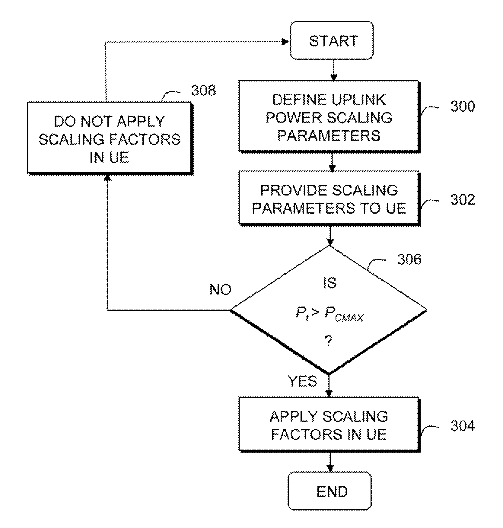
[0010]The present invention provides a network-based power scaling procedure for carrier and / or physical channel aggregation in the case of UE power limitation. In particular, an evolved NodeB (eNodeB) in the LTE-A communication network informs a UE of power limitation procedure to use when the UE exceeds its maximum transmit power. Specifically, the eNodeB informs the UE of a transmit scaling parameter to be used by the UE for each transmit channel.

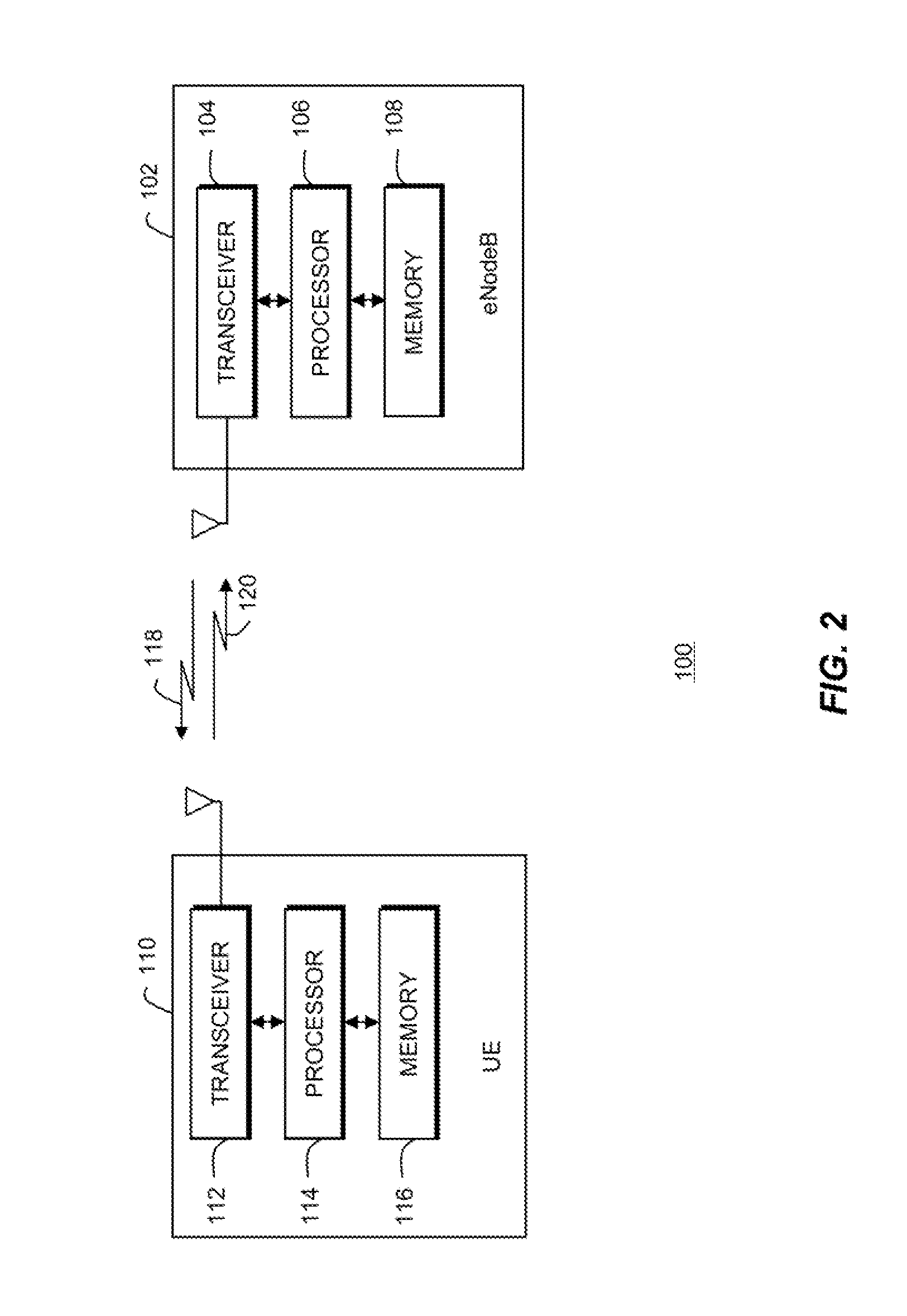
[0011]FIG. 2 is a simplified block diagram depiction of an LTE-A wireless communication system 100, in accordance with the present invention. However, it should be recognized that the present invention is also applicable to other OFDMA systems such as IEEE 802.xx-based systems, employing wireless technologies such as IEEE's 802.11, 802.16, or 802.20, modified to implement embodiments of the present invention. At present, standards bodies such as OMA (Open Mobile Alliance), 3GPP (3rd Generation Partnership Project), 3GPP2 (3rd Generation ...


PUM


Abstract

A system and method for uplink power control for aggregated channels in a communication network includes a step 300 of defining power scaling parameters to be used to derive power scaling factors to be applied to associated aggregated uplink channels. A next step 302 includes providing the power scaling parameters to user equipment. A next step 304 includes applying power scaling factors derived from the power scaling parameters to the associated aggregated uplink channels when the user equipment will exceed a maximum transmit power.

Description

TECHNICAL FIELD OF THE INVENTION[0001]This invention relates generally to wireless communication systems and more particularly to uplink power control in a communication network.BACKGROUND OF THE INVENTION[0002]In the Long Term Evolution (LTE) communication network, user equipment (UE) can only transmit one physical uplink control channel or data channel at a time. However, in the proposed LTE-Advanced (LTE-A) communication system, with aggregate carriers and / or physical channels, simultaneous transmission on multiple carrier and / or channels is supported. In addition, in LTE-A, UEs can also transmit control and data channels simultaneously on the same carrier.[0003]Referring to FIG. 1, two aggregate uplink carriers are shown in a LTE-A communication system, for example. Data channels and control channels are also represented. Since a UE can simultaneously transmit on both uplink carrier 1 and uplink carrier 2, the UE can send both control information and data at the same time. For t...

Claims


Application Information

Patent Timeline
IPC IPC(8): H04W52/04
CPCH04W52/146H04W52/34H04W52/367H04W52/32
Inventor RATASUK, RAPEEPATGHOSH, AMITABHA
Owner GOOGLE TECH HLDG LLC
Why Eureka
Try Eureka