Artificial retina device with stimulating and ground return electrodes disposed on opposite sides of the neuroretina and method of attachment

a technology of artificial retina and electrodes, applied in the field of medical devices, can solve problems such as inefficient stimulation of the neuroretina

Inactive Publication Date: 2011-09-29
PIXIUM VISION SA
View PDF53 Cites 8 Cited by
  • Summary
  • Abstract
  • Description
  • Claims
  • Application Information

AI Technical Summary

Benefits of technology

[0007]In other embodiments, each microelectrode subunit is preferably fabricated on a node of a disk-shaped silicon web, the subunits separated by open areas of the web. The open areas of the web allow nourishment and oxygen from the outer retinal circulation to diffuse into the neuroretina.
[0008]In the preferred embodiment, on the backside of the stimulating electrode unit, i.e. the side opposite the incident light side, an insulated common conductor is constructed and arranged to elect

Problems solved by technology

Placement of stimulating and ground return electrodes together in this fashion resulted in inefficient st

Method used


Image

  • Artificial retina device with stimulating and ground return electrodes disposed on opposite sides of the neuroretina and method of attachment
  • Artificial retina device with stimulating and ground return electrodes disposed on opposite sides of the neuroretina and method of attachment
  • Artificial retina device with stimulating and ground return electrodes disposed on opposite sides of the neuroretina and method of attachment

Examples


Embodiment Construction

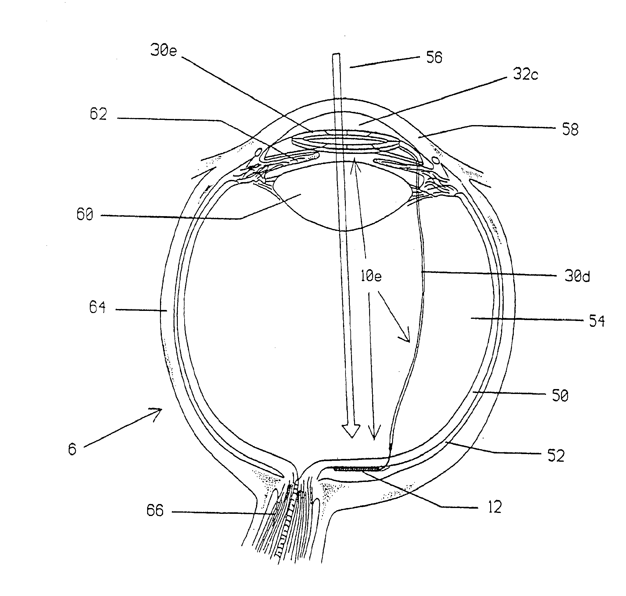
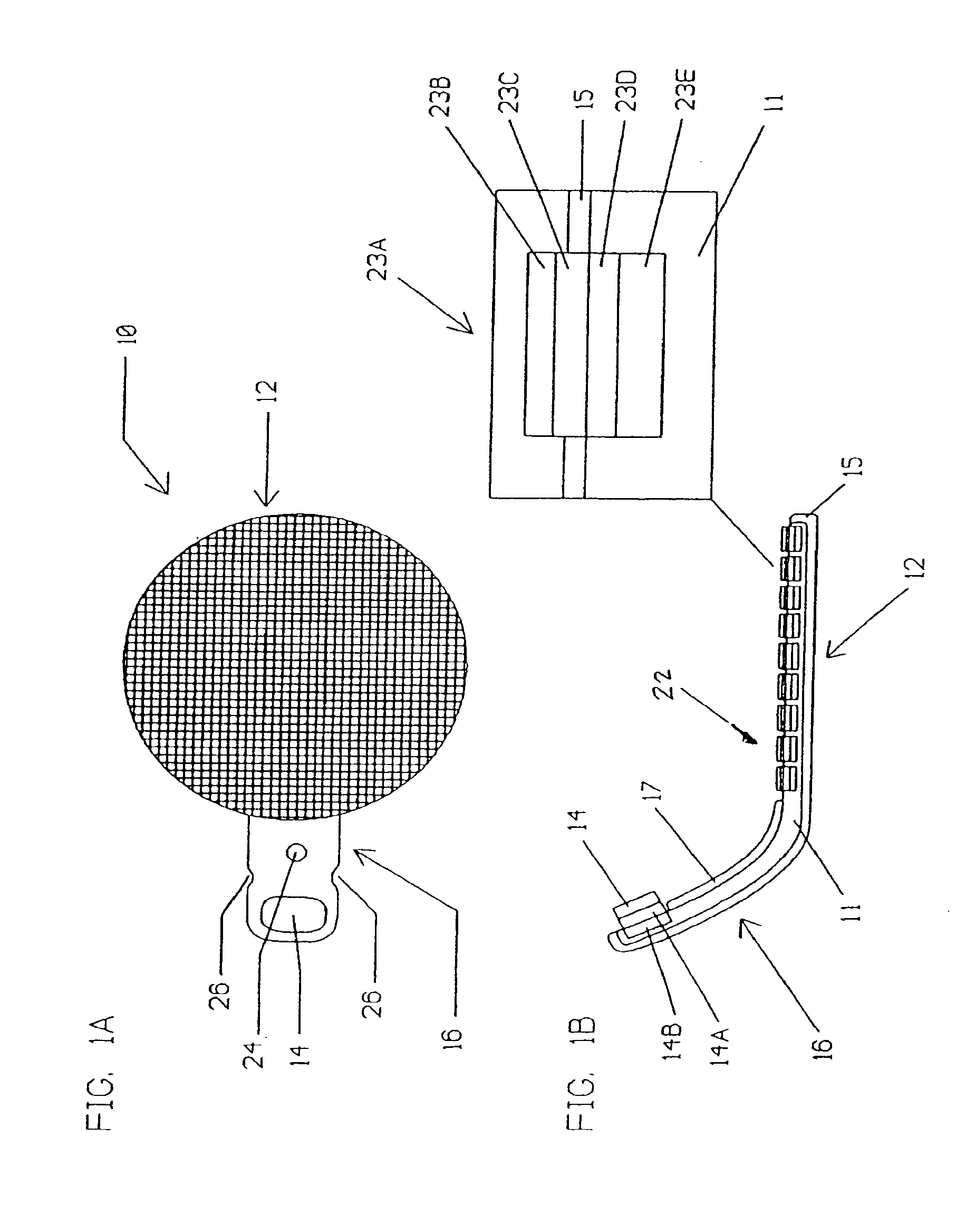
[0025]Referring to the drawings, as shown in FIGS. 1A and 1B, the preferred embodiment of retinal device 10 has a stimulating electrode unit 12 and a curved ground return electrode unit 16 configured for implantation into an eye such that the retinal device may be positioned completely inside the eye and stimulate opposite or substantially opposite sides of the neuroretina. The two components 12 and 16 are preferably physically fabricated on a single thin silicon chip substrate 11, but may be fabricated separately and then joined together. The stimulating electrode unit 12 includes an array of stimulating electrode subunits 22 each composed of one or more electrical sources such as a photodetector or photodetectors. In a preferred embodiment, the photodetectors may be implemented as microphotodiodes 23a electrically connected, for example, in series.

[0026]A stimulating electrode 23b contacts at least one of individual cells, groups of cells, portions of cells and nerve fibers of the...


PUM


Abstract

An artificial retina device to electrically stimulate a neuroretina of an eye to produce artificial vision, the artificial retina device comprising: an electrical source; at least one stimulating electrode connected with the electrical source; and at least one ground return electrode connected with the electrical source, wherein the stimulating electrode and ground return electrode are configured to be disposed within the eye on opposite sides of the neuroretina.

Description

CROSS-REFERENCE TO RELATED APPLICATIONS[0001]This application is a continuation of U.S. application Ser. No. 11 / 293,871, filed Dec. 2, 2005, which is a continuation of U.S. application Ser. No. 10 / 142,277, filed May 9, 2002, now U.S. Pat. No. 7,003,354, issued Feb. 21, 2006, which is a continuation of U.S. application Ser. No. 09 / 564,841, filed May 4, 2000, now U.S. Pat. No. 6,427,087, issued Jul. 30, 2002, which prior applications are hereby incorporated by reference in their entirety.FIELD OF THE INVENTION[0002]The present invention is generally directed to medical devices. More particularly, the present invention is directed to an artificial retina medical device and method to more efficiently stimulate electrically and with higher resolution, neuroretinal cells in partially damaged retinas to produce artificial vision. The invention provides improved efficiency and resolution of the device by using transretinal electrical current stimulation provided by stimulation and ground re...

Claims


Application Information

Patent Timeline
IPC IPC(8): A61F9/08A61F2/14A61F9/007A61N1/05A61N1/36
CPCA61F9/08A61N1/36046A61N1/0543A61F2/14
Inventor CHOW, ALAN Y.CHOW, VINCENT Y.
Owner PIXIUM VISION SA
Why Eureka
Try Eureka