Testing device and limiting switch thereof

a technology of limiting switch and testing device, which is applied in the direction of testing manufactured objects, material strength, instruments, etc., can solve the problem of damage to the shaft of the folding-type electronic devi

Inactive Publication Date: 2011-10-06
INVENTEC CORP
View PDF3 Cites 17 Cited by
  • Summary
  • Abstract
  • Description
  • Claims
  • Application Information

AI Technical Summary

Benefits of technology

[0008]The invention is directed to a testing device for testing rotation times that can be born by a shaft of a folding-type electronic device, which can be used to avoid a damage of the shaft of the folding-type electronic device caused by an excessive pivoted angle during a testing process.
[0029]According to the above descriptions, during the testing process of the testing device of the invention, the operation of the testing device can be stopped through a contact between the first rod and the first switching element of the limiting switch or a contact between the second rod and the second switching element, so as to avoid a damage of the shaft of the folding-type electronic device caused by excessive pivoted angle during the testing process. Moreover, the first switching element and the second switching element are pivotally connected to the fixed frame. In this way, when the first rod cannot be moved to contact the first switching element due to that the second switching element blocks the second rod, the second rod can temporarily push away the second switching element, so that the first rod can be moved to contact with the first switching element. Similarly, when the second rod cannot be moved to contact the second switching element due to that the first switching element blocks the first rod, the first rod can temporarily push away the first switching element, so that the second rod can be moved to contact with the second switching element.

Problems solved by technology

However, during the test process, if a pivoted angle is excessive, the shaft of the folding-type electronic device can be damaged.

Method used


Image

  • Testing device and limiting switch thereof
  • Testing device and limiting switch thereof
  • Testing device and limiting switch thereof

Examples


Embodiment Construction

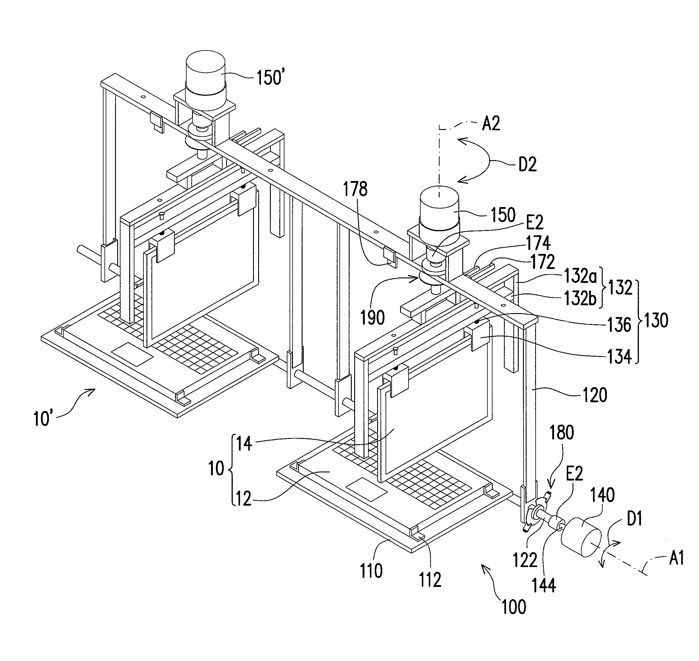
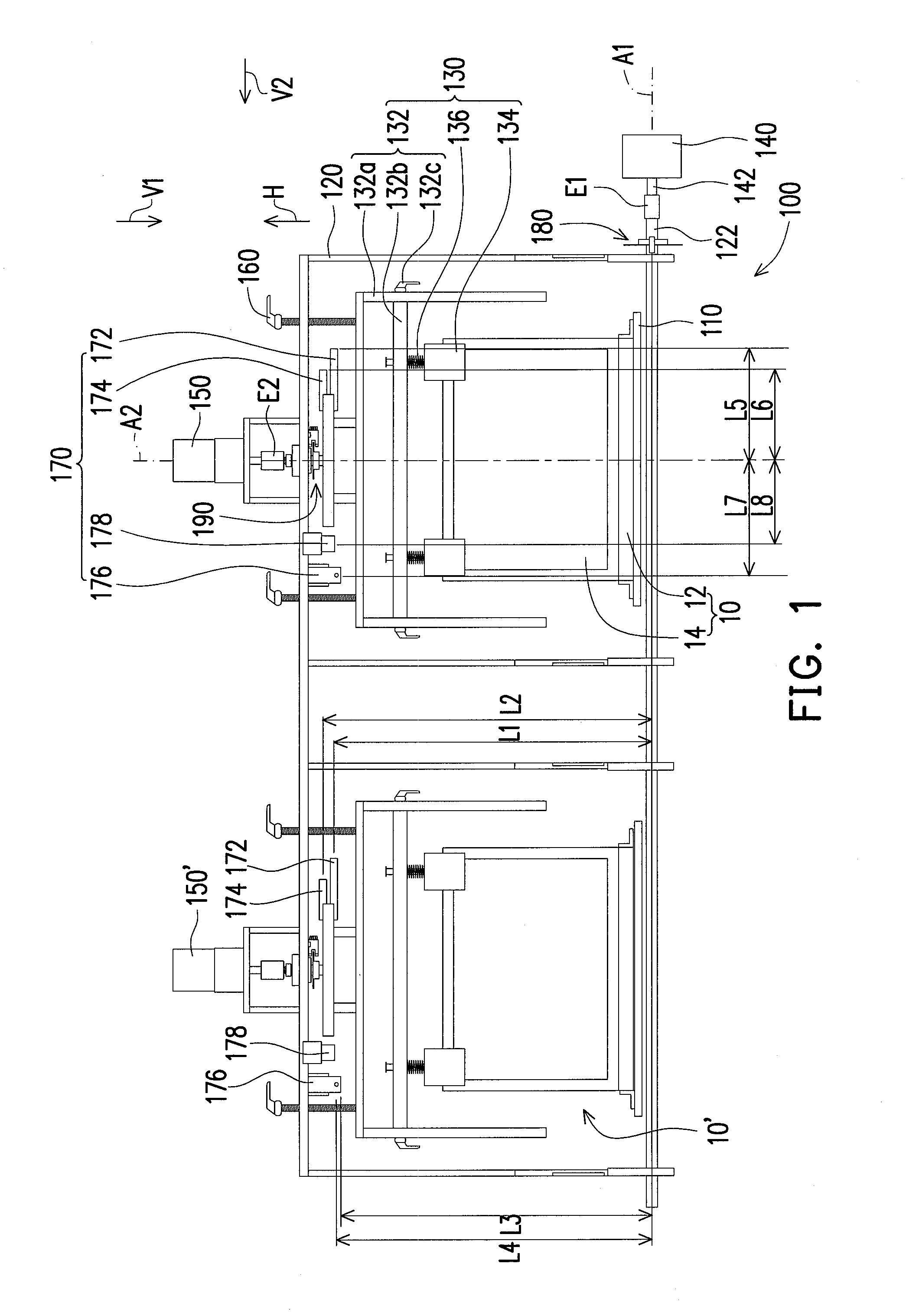
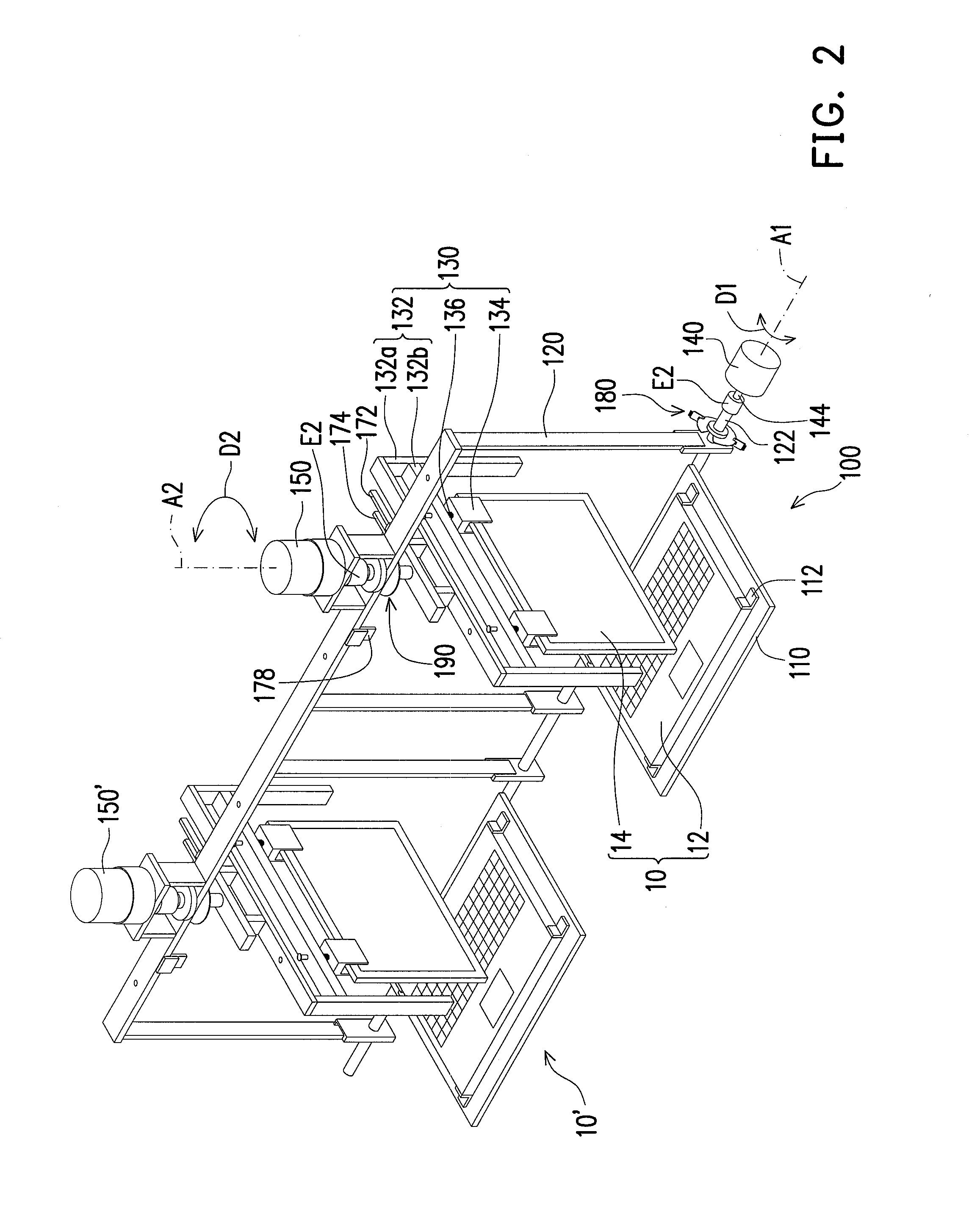
[0040]FIG. 1 is a front view of a testing device testing a folding-type electronic device according to an exemplary embodiment of the invention. FIG. 2 is a three-dimensional view of a testing device of FIG. 1 turning over a second body of the folding-type electronic device. Referring to FIG. 1 and FIG. 2, the testing device 100 is adapted to perform a rotation test of opening and closing a folding-type electronic device 10. The folding-type electronic device10 is, for example, a notebook computer, which includes a first body 12, a second body 14 and a shaft (not shown). The first body 12 is, for example, a host of the notebook computer, and the second body 14 is, for example, a display screen of the notebook computer. The shaft is connected between the first body 12 and the second body 14, so that the second body 14 can be opened or turned over relative to the first body 12 through the shaft.

[0041]The testing device 100 includes a carrier platform 110, a fixed frame 120, a clamping...


PUM

PropertyMeasurementUnit
pivoted angleaaaaaaaaaa
angleaaaaaaaaaa
pivoted angleaaaaaaaaaa

Abstract

A limiting switch suitable for a testing device is provided. The testing device includes a fixed frame and a clamping element pivoted to each other. The limiting switch includes a first rod, a second rod, a first switching element and a second switching element. The first and second rods are fixed to the clamping element. The first and second switching elements are pivotally connected to the fixed frame. When the clamping element is pivoted along a first direction, the second rod pushes the second switching element to pivot and the first rod is moved to contact with the first switching element. When the clamping element is pivoted along a second direction opposite to the first direction, the first rod pushes the first switching element to pivot and the second rod is moved to contact with the second switching element.

Description

CROSS-REFERENCE TO RELATED APPLICATION[0001]This application claims the priority benefit of Taiwan application serial no. 99110566, filed Apr. 6, 2010. The entirety of the above-mentioned patent application is hereby incorporated by reference herein and made a part of this specification.BACKGROUND[0002]1. Field of the Invention[0003]The present invention relates to a testing device and a limiting switch thereof. More particularly, the present invention relates to a testing device and a limiting switch thereof for detecting rotation times that can be born by a shaft of a folding-type electronic device.[0004]2. Description of Related Art[0005]With development of electronic technology, electronic products in the market are continually developed in order to cope with consumer's requirements of lightness, slimness and high efficiency, and various folding-type electronic devices such as notebook computers, cell phones and personal digital assistants (PDAs) have become popular in the marke...

Claims


Application Information

Patent Timeline
Patent Type & Authority Applications(United States)
IPC IPC(8): G01N3/02
CPCG01M99/008G01N2203/0282G01N2033/0078G01N3/20
Inventor HSU, NAI-RENTAI, PAO-HUACHEN, YEN-CHIHLIU, PEI-FEN
Owner INVENTEC CORP
Why Eureka
Try Eureka