
Eureka
For R&D, Eureka makes reading and utilizing patents & technical documents easy.
Eureka AIR
Designed for self-driven R&D workflows. Generate viable solutions, solve complex R&D challenges, empower your innovation with AI.

Eureka Materials
Designed for material experts only. Revolutionize your material R&D, from search, analyze, to developing new materials.

TechResearch
Generate reliable direction feasibility study reports for your R&D in just a few steps.

TechSeek
Discover and master advanced knowledge NOW. Basics, ideas, possibilities, all at once.

TechMind
As an expert in R&D Theories, TechMind can generates customized viable solutions instantly.

TechRisk
Analyze your overall solution with one click, know your potential R&D risks in advance.

TechMonitor
Get weekly tech updates, stay abreast of the latest tech innovations and key insights.
Bending of a shaft of a steerable borehole drilling tool
- Summary
- Abstract
- Description
- Claims
- Application Information
AI Technical Summary
Problems solved by technology
Method used
Image

Examples
Embodiment Construction
[0020]Certain embodiments described herein provide a steerable drilling tool having a steering mechanism enabling controlled changes in drilling direction and providing enhanced operational efficiency, among other advantages. Example directional drilling systems and associated techniques are described in U.K. Pat. Nos. 2172324, 2172325, 2177378 issued to Douglas, et al., and a publication entitled Use of a Rotary Steerable Tool at the Valhall Field, Norway, written by Sigurd Kinn, SPE, BP Norway AS and Peter Allen, SPE, Cambridge Drilling Automation Ltd and Martin Slater, SPE, BP Amoco Norway AS (IADC / SPE 59217) each of which is hereby incorporated in its entirety by reference herein.
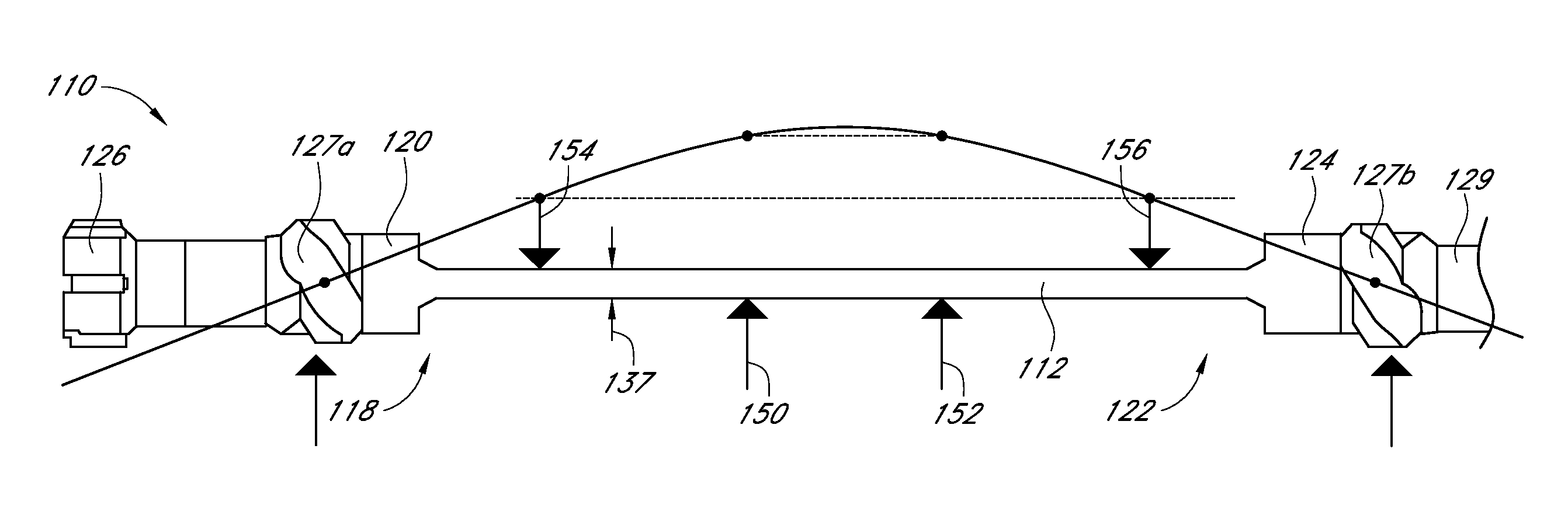
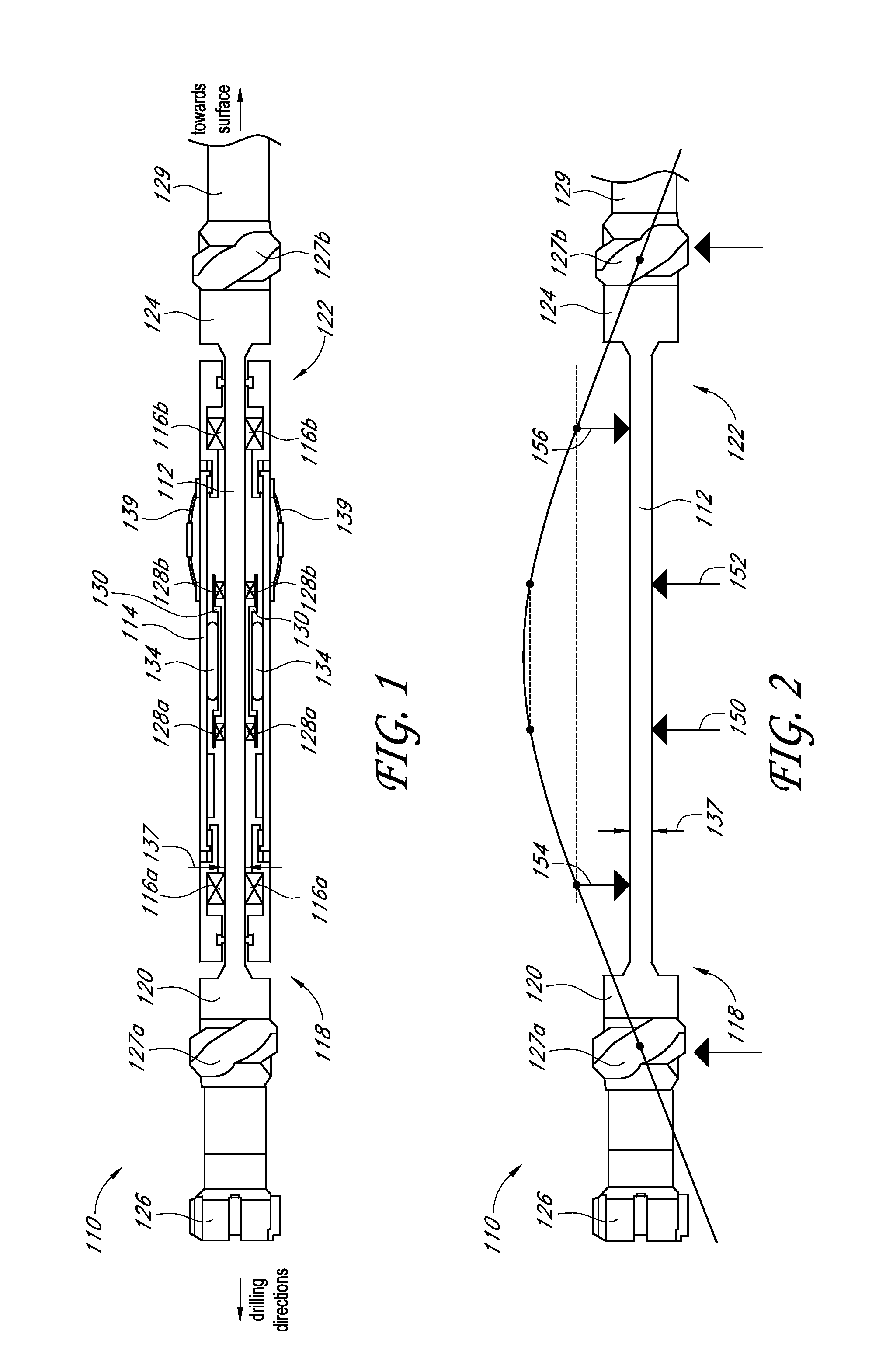
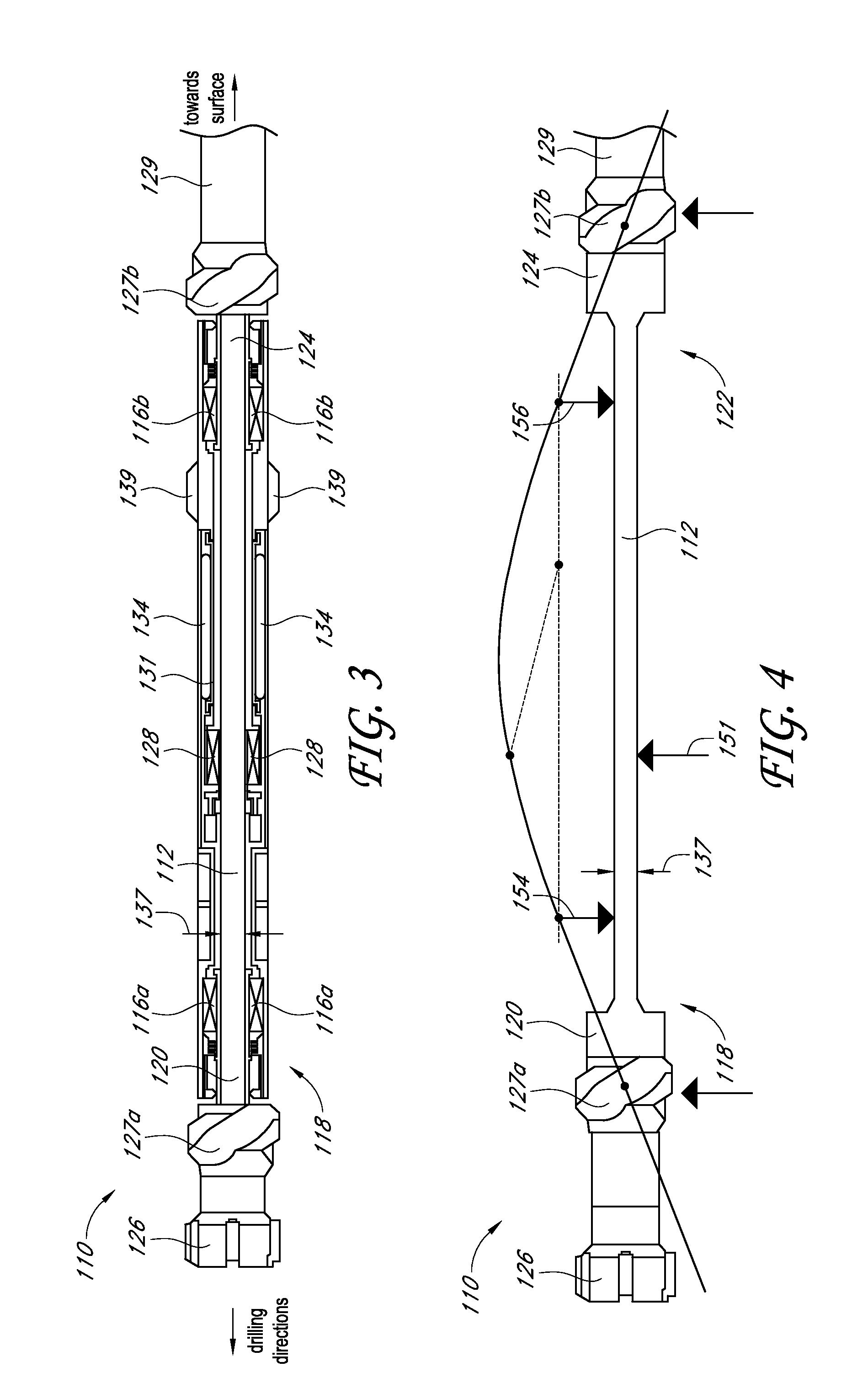
[0021]FIG. 1 schematically illustrates an example steerable drilling tool 110 having a bridge-type steering mechanism. The drilling tool 110 includes a rotating shaft 112 passing through a nominally non-rotating housing 114, where the shaft 112 and housing 114 are separated by two rotating main bearings...
PUM
 Abstract
Description
Claims
Application Information
 - R&D Engineer
- R&D Manager
- IP Professional
- Industry Leading Data Capabilities
- Powerful AI technology
- Patent DNA Extraction
Browse by: Latest US Patents, China's latest patents, Technical Efficacy Thesaurus, Application Domain, Technology Topic, Popular Technical Reports.
© 2024 PatSnap. All rights reserved.Legal|Privacy policy|Modern Slavery Act Transparency Statement|Sitemap|About US| Contact US: help@patsnap.com