Wiring substrate unit and printer including the same

Active Publication Date: 2011-10-06
BROTHER KOGYO KK
View PDF2 Cites 1 Cited by
  • Summary
  • Abstract
  • Description
  • Claims
  • Application Information

AI Technical Summary

Benefits of technology

[0008]Accordingly, an object of the present invention is to provide a wiring substrate unit which is configured to draw the wires from the input portion to the output contact points easily, which is configured to simplify the structure of the input portion, and which is configured to be expeditiously connected to the signal supply portion, and a printer provided with the wiring substrate unit.
[0020]According to the wiring substrate unit in accordance with the present invention, it is possible to draw the wire connected to the first output contact point from the first input portion and the wire connected to the second output contact point from the second input portion separately on the first wiring substrate and the second wiring substrate. Therefore, the number of wires per substrate can be decreased, and thereby it is possible to make it easy to draw the wire from the input portion to the output contact point.
[0021]Further, the first input portion or the second input portion on one of the first wiring substrate and the second wiring substrate is exposed from the cutout formed in the other of the first wiring substrate and the second wiring substrate. Therefore, it is possible to arrange one input portion and the other input portion on almost the same plane. Further, when the one input portion and the other input portion are aligned in an array, for example, it is possible to regard the two input portions as a single member and connect the two input portions to one signal supply portion. Therefore, it is possible to simplify the structure of the input portions, and thereby it is possible to expeditiously connect each of the input portions to the signal supply portion. In addition, with respect to the present invention, the alignment of the first input portion and the second input portion includes of course the alignment of the first input portion and the second input portion without interval, and the alignment of the first input portion and the second input portion at an interval.

Problems solved by technology

Thereby, it becomes complicated to draw wires from the input portion to the plurality of contact points of the wiring substrate.

Method used


Image

  • Wiring substrate unit and printer including the same
  • Wiring substrate unit and printer including the same
  • Wiring substrate unit and printer including the same

Examples


Embodiment Construction

[0039]Hereinbelow, explanations will be made with respect to a preferred embodiment of the present teaching The embodiment is an example of applying the present teaching to an ink-jet printer which has an ink-jet head for jetting ink to a recording paper.

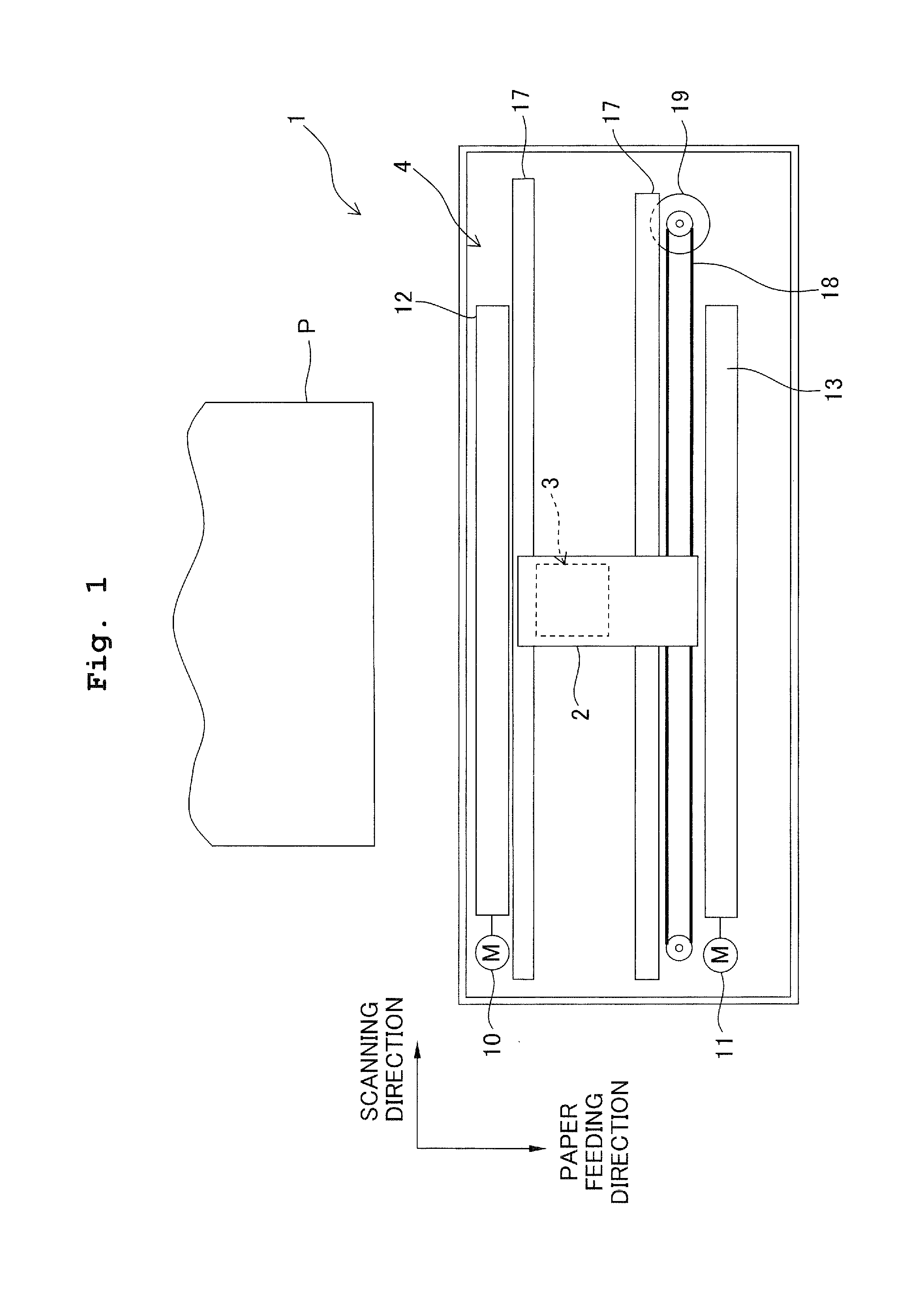
[0040]First, explanations will be made with respect to a schematic configuration of the printer of the embodiment. As shown in FIG. 1, a printer 1 mainly includes a carriage 2 constructed to be movable in a reciprocating manner along a predetermined scanning direction (a left-right direction of FIG. 1), an ink-jet head 3 provided on the carriage 2, a transport mechanism 4 for transporting a recording paper P in a paper feeding direction perpendicular to the scanning direction, a control section 5 for controlling the ink-jet head 3, the transport mechanism 4 and the like.

[0041]The carriage 2 is configured to be movable in a reciprocating manner along two guide shafts 17 extending parallel to the scanning direction (the left-right dir...


PUM


Abstract

A wiring substrate unit is provided. The unit includes: first and second wiring substrates, first and second input portions respectively formed in marginal portions of the first and second wiring substrates, and first and second output contact points respectively formed on one surfaces of the first and second wiring substrates. A through hole is formed in the first wiring substrate to correspond to the second output contact point; a cutout is formed either at a position adjacent to the first input portion of the marginal portion of the first wiring substrate or at a position adjacent to the second input portion of the marginal portion of the second wiring substrate; and one of the first and second input portions is exposed from the cutout.

Description

CROSS REFERENCE TO RELATED APPLICATION[0001]The present application claims priority from Japanese Patent Application No. 2010-082158, filed on Mar. 31, 2010, the disclosure of which is incorporated herein by reference in its entirety.BACKGROUND OF THE INVENTION[0002]1. Field of the Invention[0003]The present invention relates to a wiring substrate unit for supplying signals to a drive target (drive object) and to a printer including the wiring substrate unit.[0004]2. Description of the Related Art[0005]Conventionally, the wiring units connected to various apparatuses to supply signals thereto are known. For example, in the field of recording apparatuses provided with a great number of recording elements for recording images, characters, and the like on an object recording medium such as a recording paper, it is desired to increase the number of the recording elements and arrange them in high density in order to meet the requirements of high-speed printing and high-resolution printin...

Claims


Application Information

Patent Timeline
IPC IPC(8): B41J29/38H05K1/11H05K7/00
CPCB41J2/14233B41J2002/14491H05K2201/041H05K1/147H05K1/118
Inventor YAMASHITA, TORU
Owner BROTHER KOGYO KK
Why Eureka
Try Eureka