Imaging device and method

a technology of a wide-angle image and a camera is applied in the field of wide-angle image, which can solve problems such as difficulty in taking a wide-angle imag

Active Publication Date: 2011-10-06
FUJIFILM CORP
View PDF23 Cites 95 Cited by
  • Summary
  • Abstract
  • Description
  • Claims
  • Application Information

AI Technical Summary

Problems solved by technology

However, in a camera which takes the parallax image for the stereoscopic display, since respective optical axes of the plurality of imaging optical systems need to be aligned, it is difficult to take the wide-image in which the principal subject is shifted from the center, and also take the tele-image in which the principal subject is enlarged, at the same time.

Method used


Image

  • Imaging device and method
  • Imaging device and method
  • Imaging device and method

Examples


first embodiment

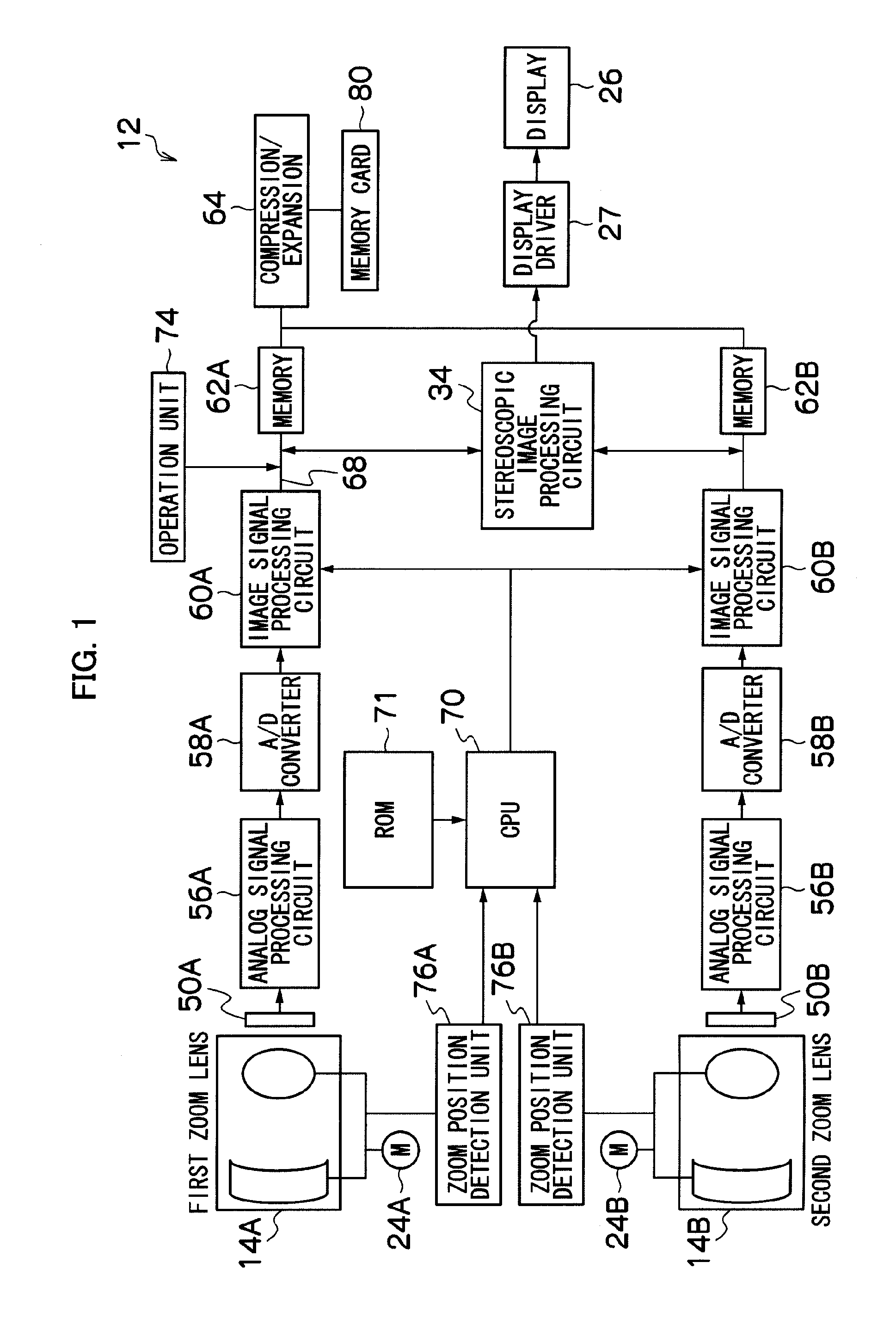
[0045]FIG. 1 illustrates an electrical configuration of a camera according to a preferred embodiment of the present invention.

[0046]Each of imaging optical systems 14A and 14B includes a zoom lens, a focus lens, an aperture and the like. It is assumed that a convergence angle between optical axes of the imaging optical systems 14A and 14B is mechanically fixed. It should be noted that three or more imaging optical systems may exist.

[0047]In response to an operation on a zoom button of an operation unit 74, lens motors 24A and 24B move the zoom lenses of the imaging optical systems 14A and 14B, along lens optical axes, to a tele side (extension side) / wide side (collapsing side), and change focal lengths (image-taking magnifications).

[0048]Although not illustrated, in an AE (Auto Exposure) operation, iris motors vary aperture values of the respective apertures of the imaging optical systems 14A and 14B so as to limit light fluxes, and thereby perform exposure adjustment. Moreover, in ...

second embodiment

[0103]In S3 and S4 of the first embodiment, compositions of the trimming wide-image and the tele-image can be easily confirmed as follows.

[0104]FIG. 7 illustrates a flowchart of a main section of the image taking process according to a second embodiment. This process can be substituted for S3 and S4 of the first embodiment.

[0105]In S11, the CPU 70 determines whether or not the release switch of the operation unit 74 has been half-pressed. If Yes, the process proceeds to S12, and if No, this determination is repeated.

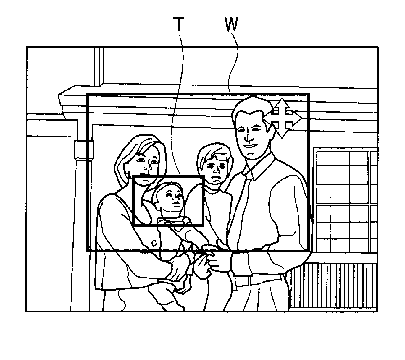
[0106]In S12, the CPU 70 enlarges an area of the trimming wide-image included in the wide-side frame W so that the area occupies the entire display 26, and displays the area on the display 26. The CPU 70 also enlarges and displays the tele-side frame T at the same display enlargement magnification as that for the wide-side frame W.

[0107]FIGS. 8A and 8B illustrate an example of the wide-side frame W and the tele-side frame T displayed in S12. FIG. 8A illustrates the displ...

third embodiment

[0111]FIG. 9 illustrates a flowchart of the main section of the image taking process according to a third embodiment.

[0112]S21 to S23 are similar to S11 to S13 of the second embodiment.

[0113]In S24, the trimming wide-image and the tele-image are obtained similarly to S14. Subsequently, the CPU 70 switches the display on the display 26 from the trimming wide-image to the tele-image.

[0114]In other words, as illustrated in FIG. 10, the default wide-image (FIG. 10A) is displayed when the image taking process is started (S2), the trimming wide-image (FIG. 10B) is displayed when the release switch is half-pressed (S21), and the tele-image (FIG. 10C) is displayed when the release switch is fully pressed (S24), sequentially.

[0115]In other words, a limit range of wide-angle image taking with the default wide-image, an image-taking range of the trimming wide-image, and an image-taking range of the tele-image can be easily confirmed.


PUM


Abstract

In a stereoscopic imaging device including a plurality of imaging optical systems, a wide-image in which a principal subject is shifted from the center is taken, and also, a tele-image in which the principal subject is enlarged is taken at the same time. A size of a wide-side frame W, that is, a size of an angle of view of a trimming wide-image is decided based on a size of a tele-side frame T, that is, a zoom magnification of a tele-side imaging optical system, a position of the wide-side frame W displayed in the decided size is arbitrarily moved depending on an instruction from an operation unit, an area delimited by the wide-side frame W moved to any position is clipped from a default wide-image, and thereby, the trimming wide-image is obtained. Thereby, the tele-image which is a telephoto image in which a desired subject is zoomed, and the trimming wide-image which is a wide-angle image in which the subject can exist at a position other than the center of the image are simultaneously obtained.

Description

BACKGROUND OF THE INVENTION[0001]1. Field of the Invention[0002]The present invention relates to an imaging device which can image a plurality of viewpoint images by a plurality of image pickup devices, and more particularly, to a technique for picking up a telephoto image and a wide-angle image of the same subject by the plurality of image pickup devices of the imaging device.[0003]2. Description of the Related Art[0004]A camera described in Japanese Patent Application Laid-Open No. 2004-207774 includes two image-taking systems which are independent from each other and generally the same, and each of which includes an imaging optical system and an imaging element. Japanese Patent Application Laid-Open No. 2004-207774 discloses that the imaging optical system includes an imaging lens, a focus lens, an aperture and the like, screens corresponding to two independent imaging systems are displayed on a display so as to be apposed, and a wide-image from the other imaging system is displa...

Claims


Application Information

Patent Timeline
Patent Type & Authority Applications(United States)
IPC IPC(8): H04N5/262H04N13/239
CPCH04N5/2258H04N5/232H04N13/0285H04N5/23296H04N13/0239H04N5/23293H04N13/286H04N13/239H04N23/45H04N23/61H04N23/635H04N23/69
Inventor MISAWA, TAKESHINAKAMURA, TOMOKAZUSAITO, KENJI
Owner FUJIFILM CORP
Why Eureka
Try Eureka