
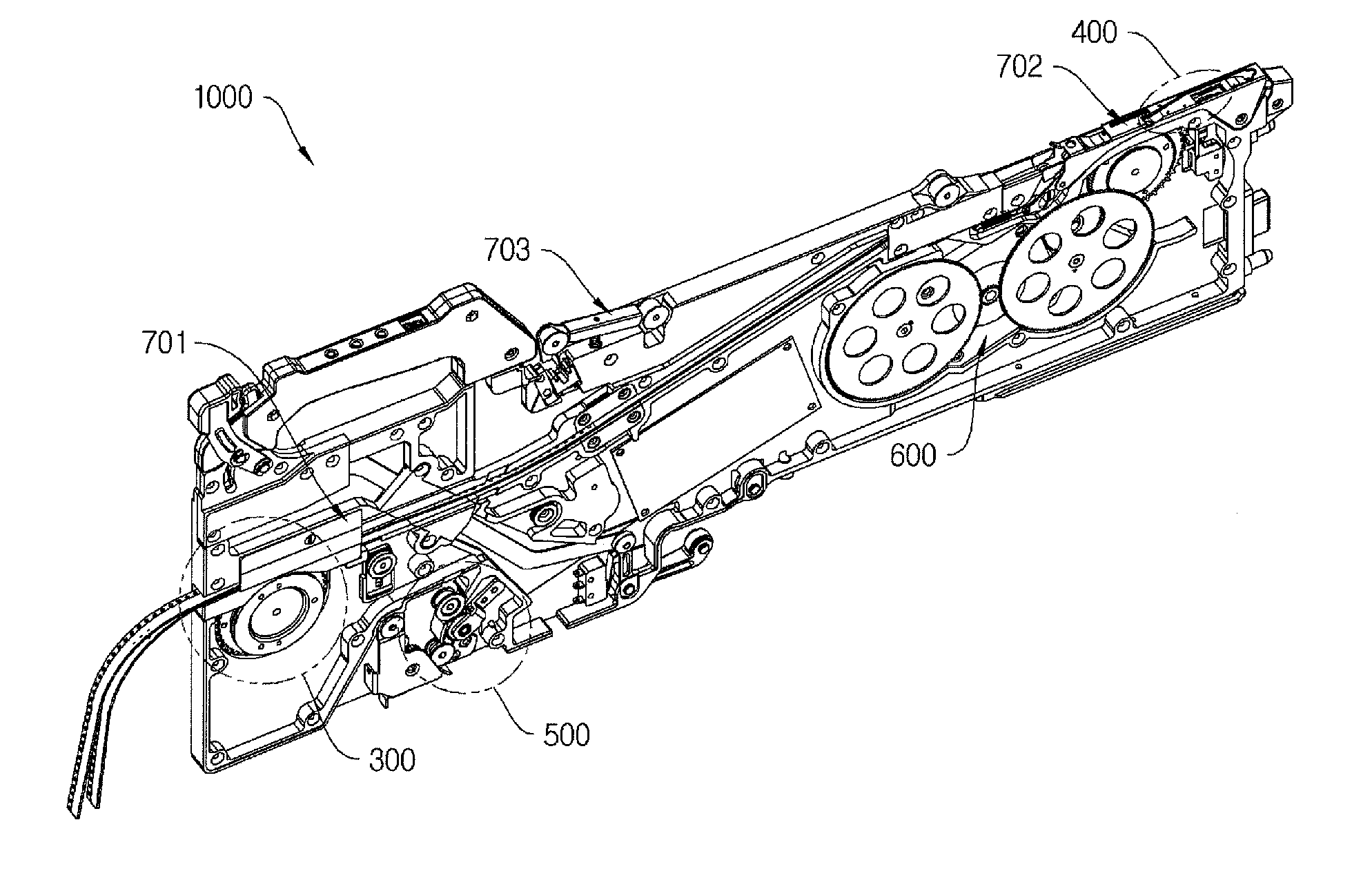
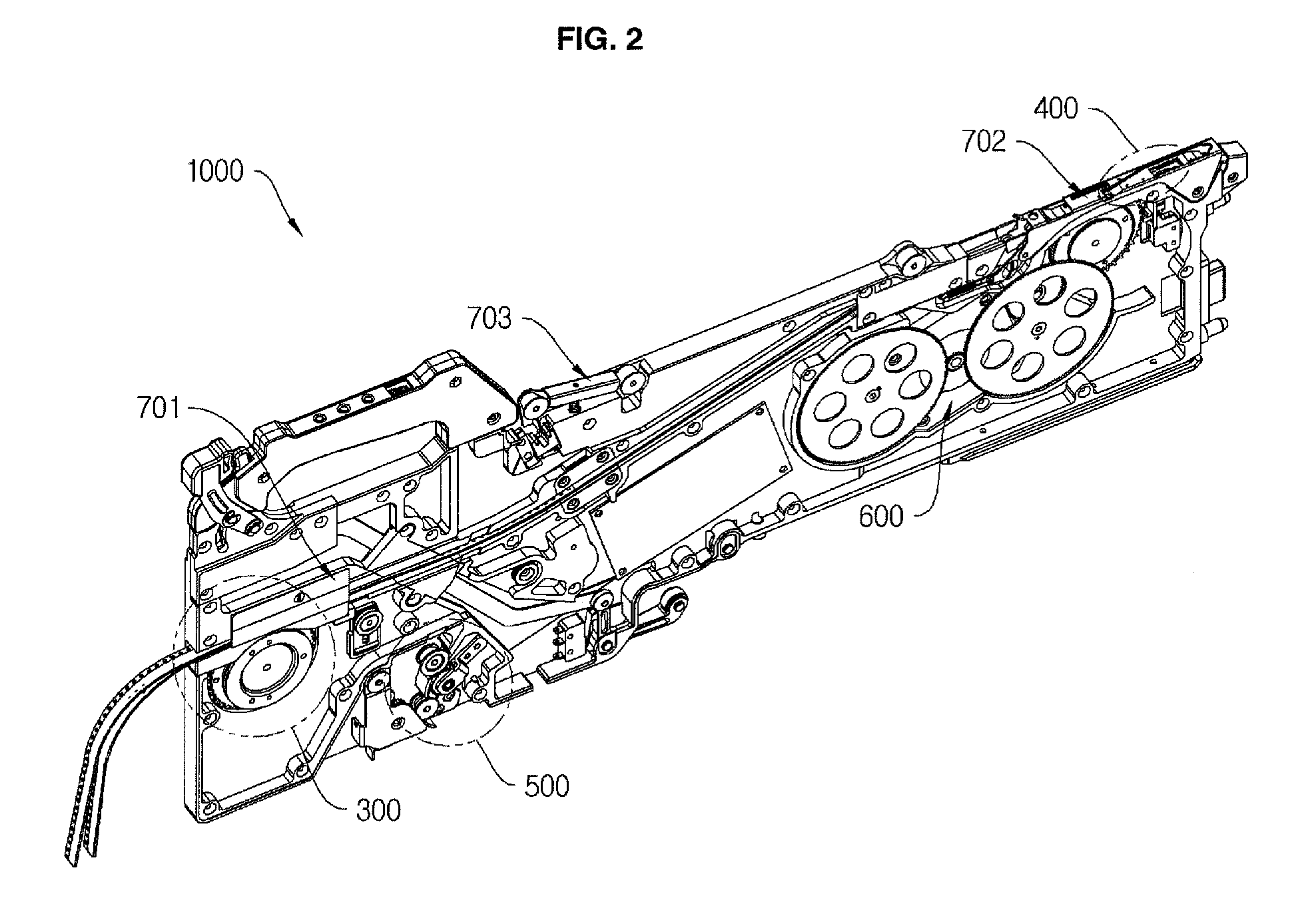
Carrier tape feeder

a feeder and carrier tape technology, applied in the direction of pile separation, transportation and packaging, packaging goods types, etc., can solve the problems of deterioration of workability, continuous feeding of carrier tapes, prolonged working time, etc., and achieve the effect of simplifying the discharge process of carrier tapes and improving productivity

Active Publication Date: 2011-10-06
STS +1
View PDF5 Cites 70 Cited by
  • Summary
  • Abstract
  • Description
  • Claims
  • Application Information

AI Technical Summary

Benefits of technology

The present invention provides a carrier tape feoder that can separate covers from bases on a long roll of material. This allows for easier handling and prevents tangling between the two materials when they are being fed out at once. It also improves efficiency by allowing multiple carriers to be loaded continuously.

Problems solved by technology

The technical problem addressed in this patent text relates to improving the efficiency and accuracy of mounting electronic chips onto printed circuit boards using carrier tapes. Current methods require frequent interruption of production due to the limited capacity of carriers, leading to increased labor costs and reduced productivity. Additionally, current designs result in issues like static electricity and difficulty in accurate part placement when using multiple carriers.

Method used


Image

  • Carrier tape feeder
  • Carrier tape feeder
  • Carrier tape feeder

Examples


Embodiment Construction

[0038]Exemplary embodiments of the present invention will now be described in detail.

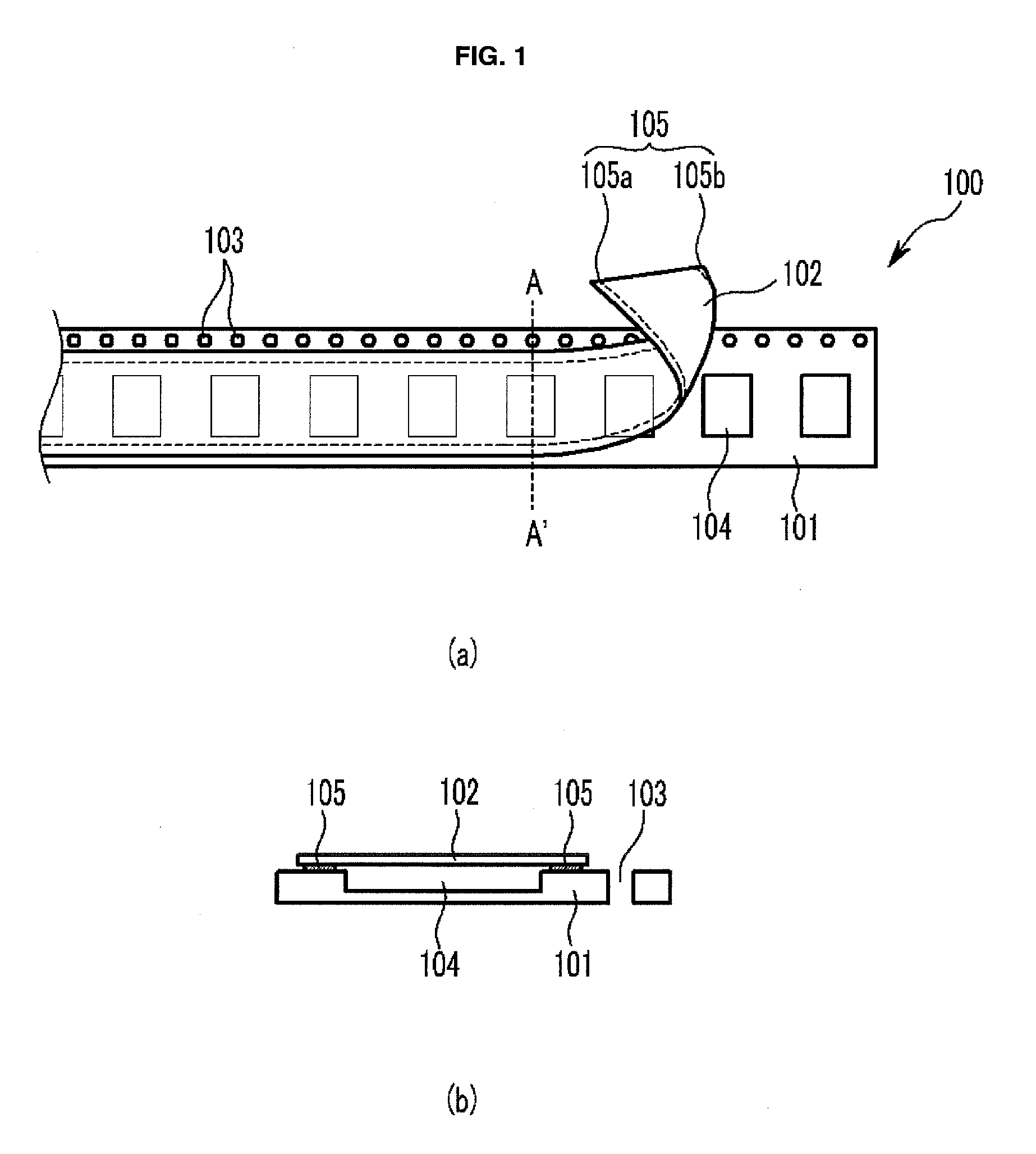
[0039]The present invention provides a carrier tape feeder including a unit for loading a carrier tape, a picking-up unit and a driving unit, wherein the pick-up unit includes a knife portion for separating a cover tape from a base tape in a first adhesive portion, a folding-guiding portion spaced from one lateral side of the knife portion to induce folding of the cover tape separated by the knife portion in the lengthwise direction in a state in which the cover tape is partially attached to the base tape in a second adhesive portion, and an inversion-guiding portion extending in an oblique direction from the knife portion and the folding-guiding portion toward the outside of the carrier tape to induce inversion of the upper and lower surfaces of the cover tape folded in the folding-guiding portion so as to be superimposed on the base tape, and wherein the distal end of the lateral side of the foldi...


PUM


Abstract

A carrier tape feeder is provided. The carrier tape feeder includes a unit for loading a carrier tape, a picking-up unit where chips are picked up, and a driving unit. The pick-up unit includes a knife portion, a folding-guiding portion, and an inversion-guiding portion. The knife portion separates a cover tape from a base tape in a first adhesive portion. The folding-guiding portion is spaced from one lateral side of the knife portion to induce folding of the cover tape separated by the knife portion in the lengthwise direction in a state in which the cover tape is partially attached to the base tape in a second adhesive portion. The inversion-guiding portion extends in an oblique direction from the knife portion and the folding-guiding portion toward the outside of the carrier tape to induce inversion of the upper and lower surfaces of the cover tape folded in the folding-guiding portion so as to be superimposed on the base tape. The distal end of the lateral side of the folding-guiding portion opposed to the knife portion extends above the second adhesive portion.

Description


Claims


Application Information

Patent Timeline
Owner STS
Learn More