Joint sleeve for a rotor blade assembly of a wind turbine

a technology for wind turbines and joints, which is applied in the direction of liquid fuel engines, vessel construction, marine propulsion, etc., can solve the problems of difficult to accurately align the blade tip with the rest of the rotor blade, manual installation, and complex known attachment devices

Inactive Publication Date: 2011-10-06
GENERAL ELECTRIC CO
View PDF15 Cites 67 Cited by
  • Summary
  • Abstract
  • Description
  • Claims
  • Application Information

AI Technical Summary

Problems solved by technology

However, known attachment devices are typically complex and are manually intensive to install.
Additionally, suc

Method used


Image

  • Joint sleeve for a rotor blade assembly of a wind turbine
  • Joint sleeve for a rotor blade assembly of a wind turbine
  • Joint sleeve for a rotor blade assembly of a wind turbine

Examples


Embodiment Construction

[0019]Reference now will be made in detail to embodiments of the invention, one or more examples of which are illustrated in the drawings. Each example is provided by way of explanation of the invention, not limitation of the invention. In fact, it will be apparent to those skilled in the art that various modifications and variations can be made in the present invention without departing from the scope or spirit of the invention. For instance, features illustrated or described as part of one embodiment can be used with another embodiment to yield a still further embodiment. Thus, it is intended that the present invention covers such modifications and variations as come within the scope of the appended claims and their equivalents.

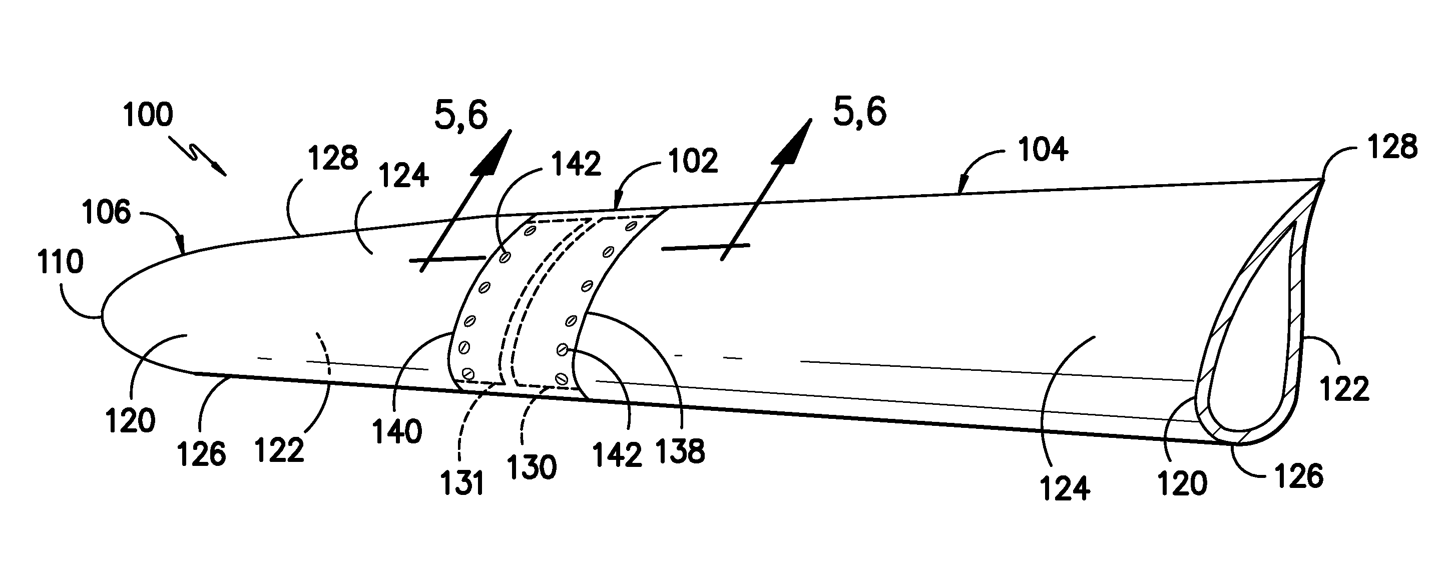
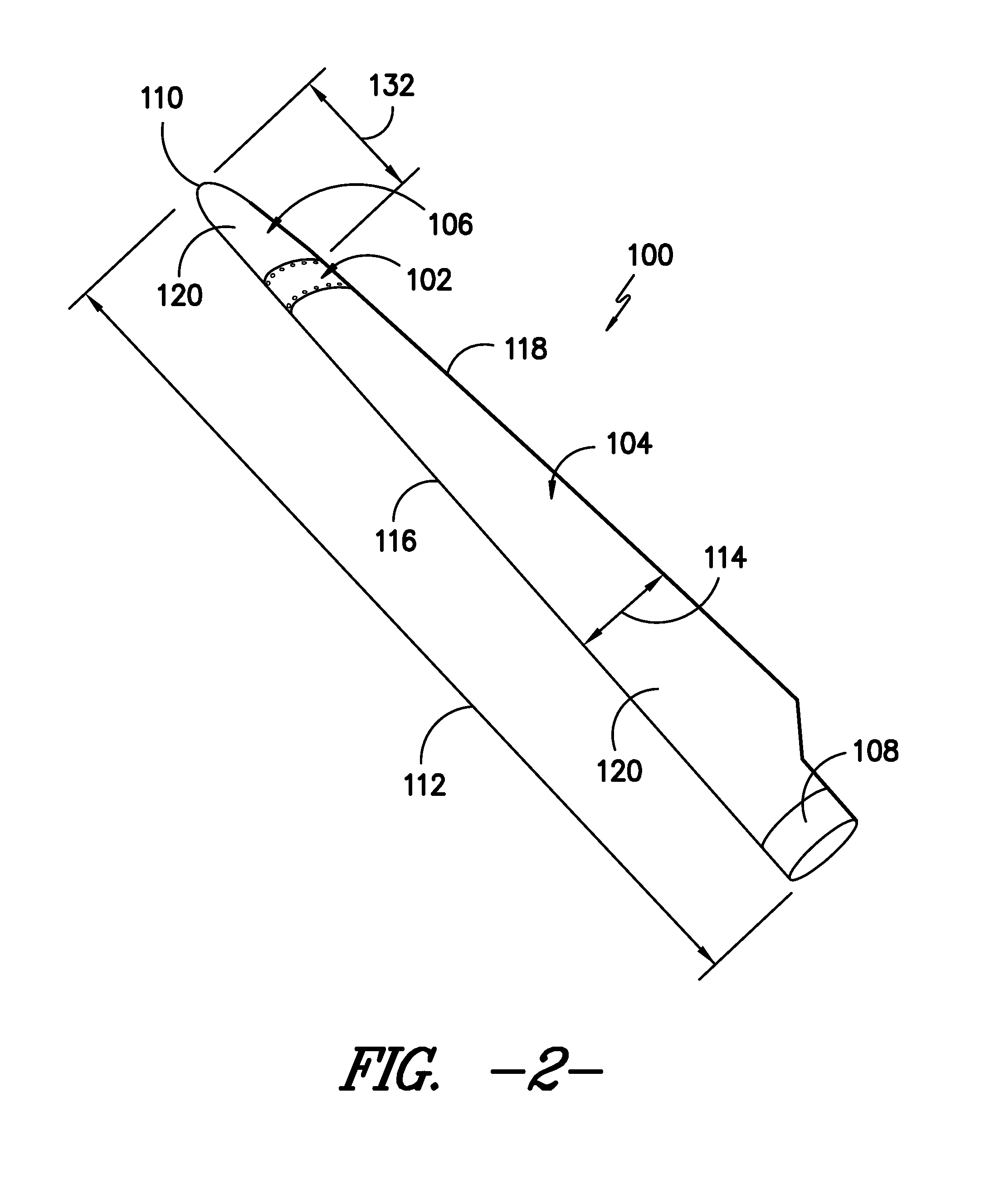
[0020]In general, the present subject matter is directed to a joint sleeve for joining together blades sections of a rotor blade assembly. In particular, the joint sleeve may define a cavity configured to receive an end of each blade section. For example, t...


PUM


Abstract

A joint sleeve for assembling together a first blade section and a second blade section of a rotor blade assembly is disclosed. The joint sleeve may include an outer surface and an inner surface defining a cavity. The cavity may be configured to receive a joint end of the first blade section and a joint end of the second blade section. The joint sleeve may also include a plurality of openings defined between the outer and inner surfaces. The openings may be configured to receive fasteners for securing the joint ends of the first and second blade sections within the cavity. Additionally, a profile of the outer surface may be configured to generally correspond to an aerodynamic profile of the first and second blade sections such that a substantially continuous aerodynamic profile is defined between the first and second blade sections when the joint ends are inserted within the cavity.

Description

FIELD OF THE INVENTION[0001]The present subject matter relates generally to rotor blades of a wind turbine and, more particularly, to a joint sleeve for joining blade sections of a rotor blade assembly.BACKGROUND OF THE INVENTION[0002]Wind power is considered one of the cleanest, most environmentally friendly energy sources presently available, and wind turbines have gained increased attention in this regard. A modern wind turbine typically includes a tower, generator, gearbox, nacelle, and one or more rotor blades. The rotor blades capture kinetic energy from wind using known foil principles and transmit the kinetic energy through rotational energy to turn a shaft coupling the rotor blades to a gearbox, or if a gearbox is not used, directly to the generator. The generator then converts the mechanical energy to electrical energy that may be deployed to a utility grid.[0003]To ensure that wind power remains a viable energy source, efforts have been made to improve the overall perform...

Claims


Application Information

Patent Timeline
IPC IPC(8): F04D29/18
CPCF03D1/0675F03D1/0683Y02E10/721F05B2260/301F05B2250/292F05B2240/302Y02E10/72F05B2240/307
Inventor BELL, ERIC LEE
Owner GENERAL ELECTRIC CO
Why Eureka
Try Eureka