Rod and plate system for incremental reduction of the spine

a technology of spinal column and plate, which is applied in the field of polyaxial spinal stabilizer and/or alignment system, can solve the problems of difficult surgeons' attachment of rods or plates to screws, inability of plating systems to be used in certain patients and/or for treatment of certain pathologies, and difficulty in the transfer of spinal column load to the stabilizer through the connection between rods and screws

Inactive Publication Date: 2011-10-06
PERUMALA HLDG LLC A BELIZE LLC
View PDF3 Cites 37 Cited by
  • Summary
  • Abstract
  • Description
  • Claims
  • Application Information

AI Technical Summary

Benefits of technology

The present invention provides solutions for the above-described problems by providing a screw cap for use in a system for aligning and/or stabilizing the spinal column comprising a pedicle screw, a threaded nut, and either a rod or a plate. The screw cap comprises a base having a bore therethrough for receiving the head of a pedicle screw and a riser formed thereon for re...

Problems solved by technology

A problem that arises during surgical implantation of such systems involves attachment of the screw to the rod.
For this reason, it can be difficult for the surgeon to attach the rod or plate to the screws, particularly when the patient suffers from spinal deformity.
Of course the plate of a plating system cannot be formed or bent to align to the screws with the result that plating systems cannot be used in certain patients and/or for treatment of certain ...

Method used


Image

  • Rod and plate system for incremental reduction of the spine
  • Rod and plate system for incremental reduction of the spine
  • Rod and plate system for incremental reduction of the spine

Examples


first embodiment

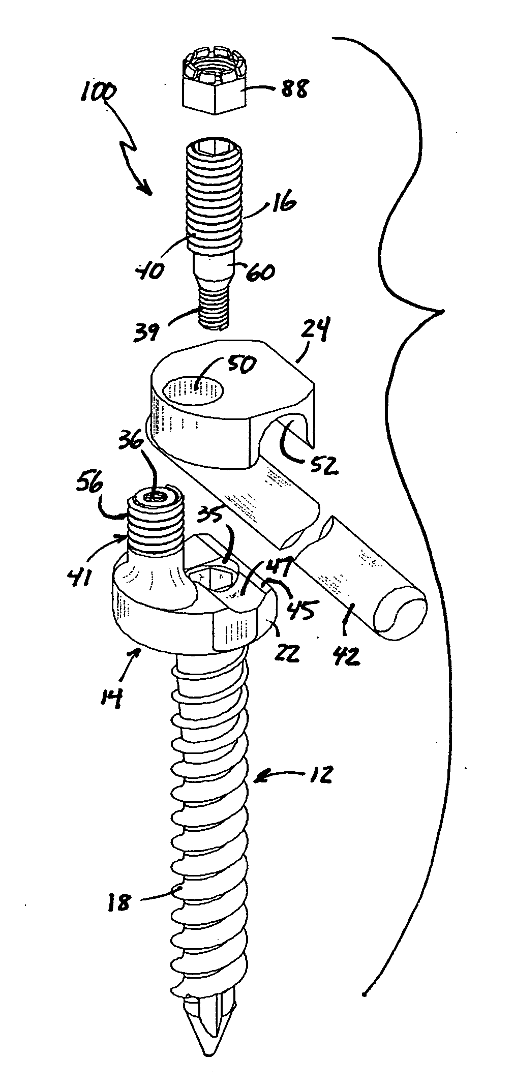
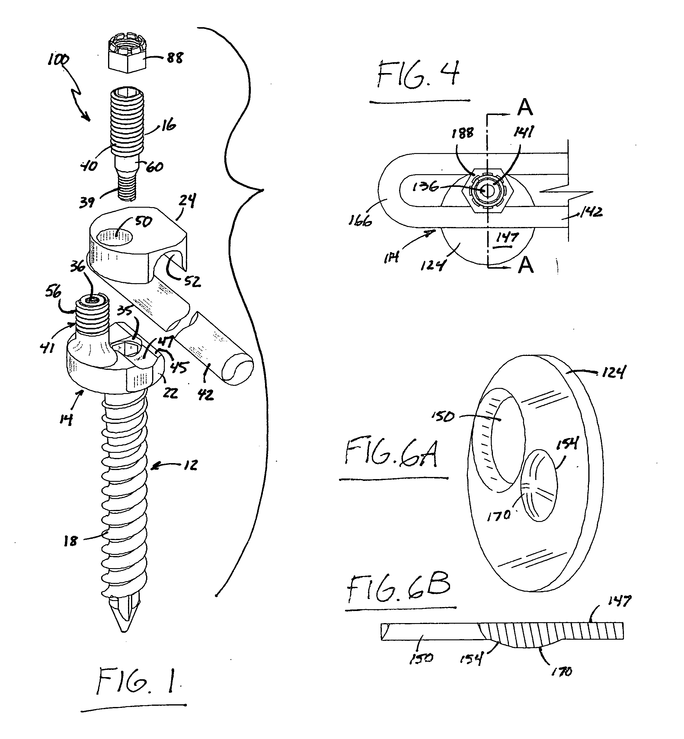
In more detail, FIGS. 1-3 show an apparatus, indicated generally at reference numeral 10, for aligning and / or stabilizing the spinal column constructed in accordance with the present invention. Apparatus 10 is comprised of pedicle screw 12 and screw cap 14, screw 12 being of a type known in the art comprised of an elongate threaded shank 18 and head 20. Screw cap 14 is comprised of base 22 and washer 24, with means 26 formed in base 22 for retaining screw cap 14 to the head 20 of screw 12. As shown in FIGS. 3C and 3D, screw cap retaining means 26 takes the form of a cavity 28 formed in the base 22 of screw cap 14, cavity 28 being sized so as to receive the rounded head 20 of screw 12 therein while allowing screw cap 14 to be positioned in an unlimited number of positions relative to screw 12 during surgical fixation to the patient's vertebral body such that the cavity 28 and the head 20 of screw 12 function in a manner similar to a ball and socket joint. The ability to position scre...

second embodiment

In a second embodiment shown in FIGS. 4-6 in which reference numerals corresponding to the reference numerals of the component parts shown in FIGS. 1-3 are designated by like reference numerals preceded by a “1,” the apparatus is indicated generally at reference numeral 110. Screw cap 114 is comprised of base 122 and washer 124, base 124 being provided with a bore 128 extending therethrough and riser 141, and as best shown in FIG. 4, the longitudinal axis (not labeled in the figures) of riser 141 is laterally offset from the central axis (also not labeled) of bore 128 in the same manner as described above in connection with the embodiment shown in FIGS. 1-3. Washer 124 is formed in the shape of a right circular cylinder and is comprised of bore 150 (FIG. 6) through which riser 141 is received (see FIG. 5) and surface 147 adapted for engaging plate 166. Referring also to FIGS. 5 and 6, it can be seen that washer 124 is provided with a raised area 154 that drops into the opening 135 (...

third embodiment

the apparatus of the present invention is indicated generally at reference numeral 210 and shown in FIGS. 7-10 and the component parts of apparatus 210 are designated with the same reference numerals used for the corresponding parts of apparatus 10 shown in FIGS. 1-6, but preceded by a “2.” Screw cap 214 is comprised of base 222 and washer 224, base 224 being provided with a bore 228 extending therethrough and an upright riser 241, and as best shown in FIG. 6, the longitudinal axis (not labeled) of riser 241 is laterally offset from the central axis (also not labeled) of bore 228 in the same manner as described above in connection with the embodiment shown in FIGS. 1-6. Washer 224 is comprised of a bore 250 through which riser 241 is received and a surface 247 adapted for engaging plate 266. Referring to FIGS. 8 and 9, it can be seen that washer 224 is provided with a raised area 254 that drops into the opening 235 of the cavity, or bore, 228 through the base 222 of screw cap 214 an...


PUM


Abstract

Apparatus for use in stabilizing and/or aligning the spinal column utilizes hooks and rods to effectively transfer load from the vertebrae to the apparatus regardless of the angle and the height of the pedicular screws. A screw cap formed of a base having a bore therethrough for receiving the head of the screw, an upright riser formed thereon that is laterally offset from the bore, and a surface for engaging the rod or plate of the stabilizer enables the apparatus to be used for stabilizing and/or aligning vertebral bodies that are out of alignment, of different shape or size, and/or pathology. The apparatus is implanted in a series of steps that are quickly and conveniently performed in the surgical stage and with minimal application of force to align the vertebral bodies, decreasing the likelihood of damaging the nerves populating the surgical stage.

Description

BACKGROUND OF THE INVENTIONThe present invention relates to alignment and / or stabilizing of the spinal vertebrae. More specifically, the present invention relates to a polyaxial spinal stabilizer and / or alignment system that effectively transfers the load from the vertebrae to the stabilizer using structure that facilitates surgical implantation of the system.Stabilization and / or alignment of the spinal column is indicated for treatment of many pathologies including trauma, tumor, infection, degenerative spine disease, congenital, iatrogenic spinal instability, spondylolysis / spondylolisthesis, pseudarthrosis, kyphosis, scoliosis, and / or other spinal deformity. A number of stabilizers for treating such pathologies that utilize “hook and rod” components are disclosed in the scientific and patent literature and are available from such vendors as Sofamor-Danek, Osteonics, and others. Such stabilizers utilize screws that are driven into the bodies of adjacent vertebrae, typically in the ...

Claims


Application Information

Patent Timeline
IPC IPC(8): A61B17/70A61B17/88
CPCA61B17/7001A61B17/7041A61B17/7037A61B17/7007
Inventor PISHARODI, MADHAVAN
Owner PERUMALA HLDG LLC A BELIZE LLC
Why Eureka
Try Eureka