Turbo refrigerator

Inactive Publication Date: 2011-10-13
IHI CORP
View PDF5 Cites 5 Cited by
  • Summary
  • Abstract
  • Description
  • Claims
  • Application Information

AI Technical Summary

Benefits of technology

[0015]According to the invention, since the braking device operates the electric motor as a generator, the reversal of the impeller is braked. Accordingly, the reversal of the turbo compressor can be prevented or suppressed. Moreover, as the braking device is provided, the revers

Problems solved by technology

Therefore, there is a possibility of the impeller of the turbo

Method used


Image

  • Turbo refrigerator
  • Turbo refrigerator

Examples


Example

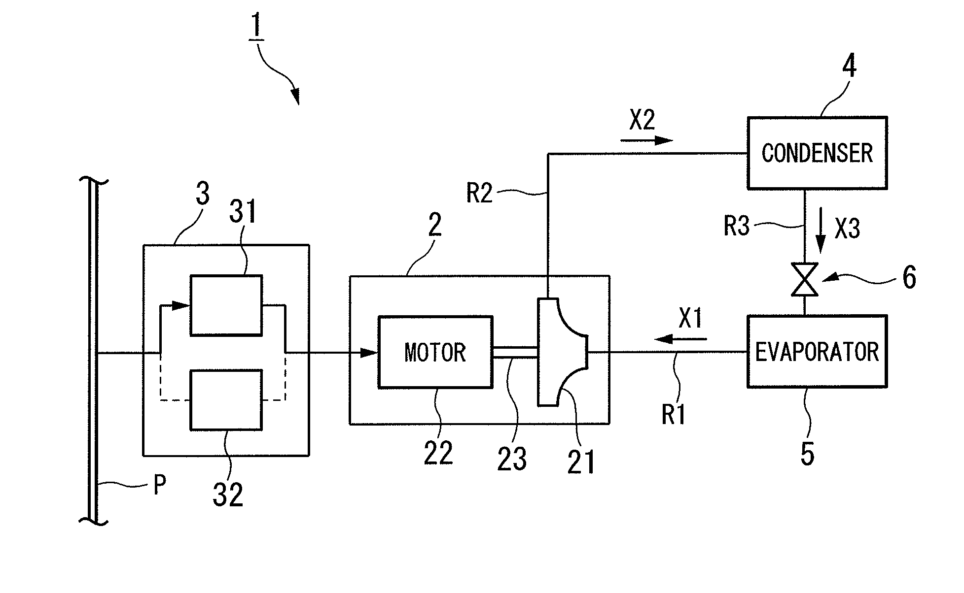
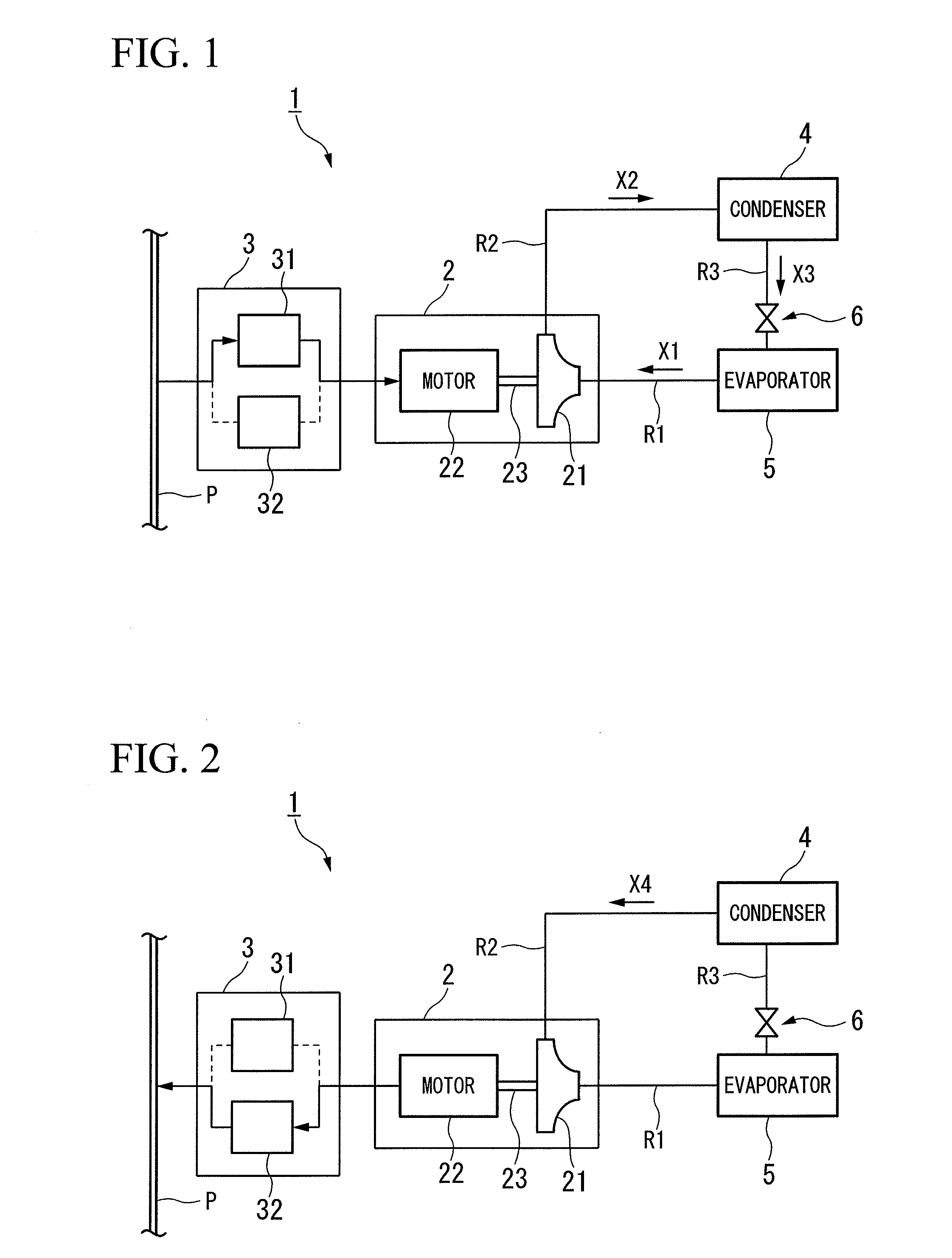
[0018]Hereinafter, exemplary embodiments of the invention will be described with reference to FIGS. 1 to 2. As well, in the drawings used for the following description, in order to allow each member to have a recognizable size, the scale of each member is appropriately changed.

[0019]FIG. 1 is a block diagram showing a skeleton framework of a turbo refrigerator 1 according to an embodiment of the invention.

[0020]The turbo refrigerator 1 according to this embodiment is installed, for example, at a building, a factory, or the like in order to generate cooling water for air-conditioning. In addition, the turbo refrigerator 1 in this embodiment includes a turbo compressor 2, an inverter 3 (braking device), a condenser 4, and an evaporator 5.

[0021]The turbo compressor 2 is a member that compresses a refrigerant gas X1 which is a refrigerant in a gaseous state to generate a compressed refrigerant gas X2. A first flow path R1 through which the refrigerant gas X1 flows and a second flow path...


PUM


Abstract

A turbo refrigerator includes a condenser that cools and liquefies a compressed refrigerant, an evaporator that vaporizes the liquefied refrigerant and takes away heat of vaporization from a cooling object, thereby cooling the cooling object, and a turbo compressor that compresses the refrigerant vaporized by the evaporator by rotation of an impeller driven to rotate by an electric motor, and supplies the compressed refrigerant to the condenser. Moreover, the turbo refrigerator includes a braking device that operates the electric motor as a generator when the impeller is urged to rotate by the vaporized refrigerant, so as to brake the rotation of the impeller.

Description

BACKGROUND OF THE INVENTION[0001]1. Field of the Invention[0002]The present invention relates to a turbo refrigerator.[0003]Priority is claimed on Japanese Patent Application No. 2010-092314, filed on Apr. 13, 2010, the content of which is incorporated herein by reference.[0004]2. Description of Related Art[0005]As a refrigerator that cools or freezes cooling objects such as water, a turbo refrigerator having a turbo compressor that compresses and discharges a refrigerant in a gaseous state is known (for example, refer to Japanese Patent Application, Publication No. 2007-177695). The turbo compressor compresses the refrigerant by the rotation of an impeller which is driven to rotate by an electric motor.[0006]The refrigerant compressed by the turbo compressor is supplied to a condenser and then is cooled and liquefied. The liquefied refrigerant is supplied to an evaporator and is thus vaporized by the evaporator. The refrigerant takes away heat of vaporization from a cooling object ...

Claims


Application Information

Patent Timeline
IPC IPC(8): F25B1/00
CPCF25B1/053
Inventor SUGITANI, NORIYASUFUJISAKU, KATSUYA
Owner IHI CORP
Why Eureka
Try Eureka