Tracheostoma plaster

a tracheostoma and plaster technology, applied in the field of tracheostoma plaster, can solve the problems of inferior lung capacity or need of respiratory treatment, inability to obtain enough air, and inability to achieve normal nasal function

Active Publication Date: 2011-10-13
COLOPLAST AS
View PDF4 Cites 10 Cited by
  • Summary
  • Abstract
  • Description
  • Claims
  • Application Information

AI Technical Summary

Benefits of technology

[0012]Accordingly, the present invention preferably seeks to mitigate, alleviate or eliminate one or more of the above-identified deficiencies in the art and disadvantages singly or in any combination and solves at least the above mentioned problems by providing a device for holding a tracheostoma device over a tracheostoma of a patient, said device comprising: a tubular portion, having a distal and a proximal opening, for receiving the tracheostoma device in the ...

Problems solved by technology

A tracheostomy is performed for example when there is a malfunction, such as a result from injury or disorder, in respect of the nervous system or the respiratory passages, which malfunction results in an incapacity to obtain enough air.
An inferior lung capacity or need of respiratory treatment may also result in a tracheostomy.
After this procedure, normal nasal function is not possible.
However, this tape is accompanied by the drawbacks that the adhesive area towards the patient is limited by the area of the tracheostoma device holder.
Thus, it is difficult to adhere this system in pit in between the sternocleidomastoid muscles, at patients with sunken stomas, i.e. stomas that somewhat sunken into the throat of the patient, since the adhesive surface of the system inevitably will adhere to the walls of the pit before reaching the bottom of the pit with the central portion of the system.
Thus, this system is only suitable for mildly or non-sunken stomas.
Furthermore, due to the stiffness needed to withstand flipping over at high speech pressure, the circular shape of the rigid portion...

Method used


Image

  • Tracheostoma plaster
  • Tracheostoma plaster
  • Tracheostoma plaster

Examples


Embodiment Construction

[0021]The following description focuses on an embodiment of the present invention applicable to a system for holding a tracheostoma device over a tracheostoma of a patient.

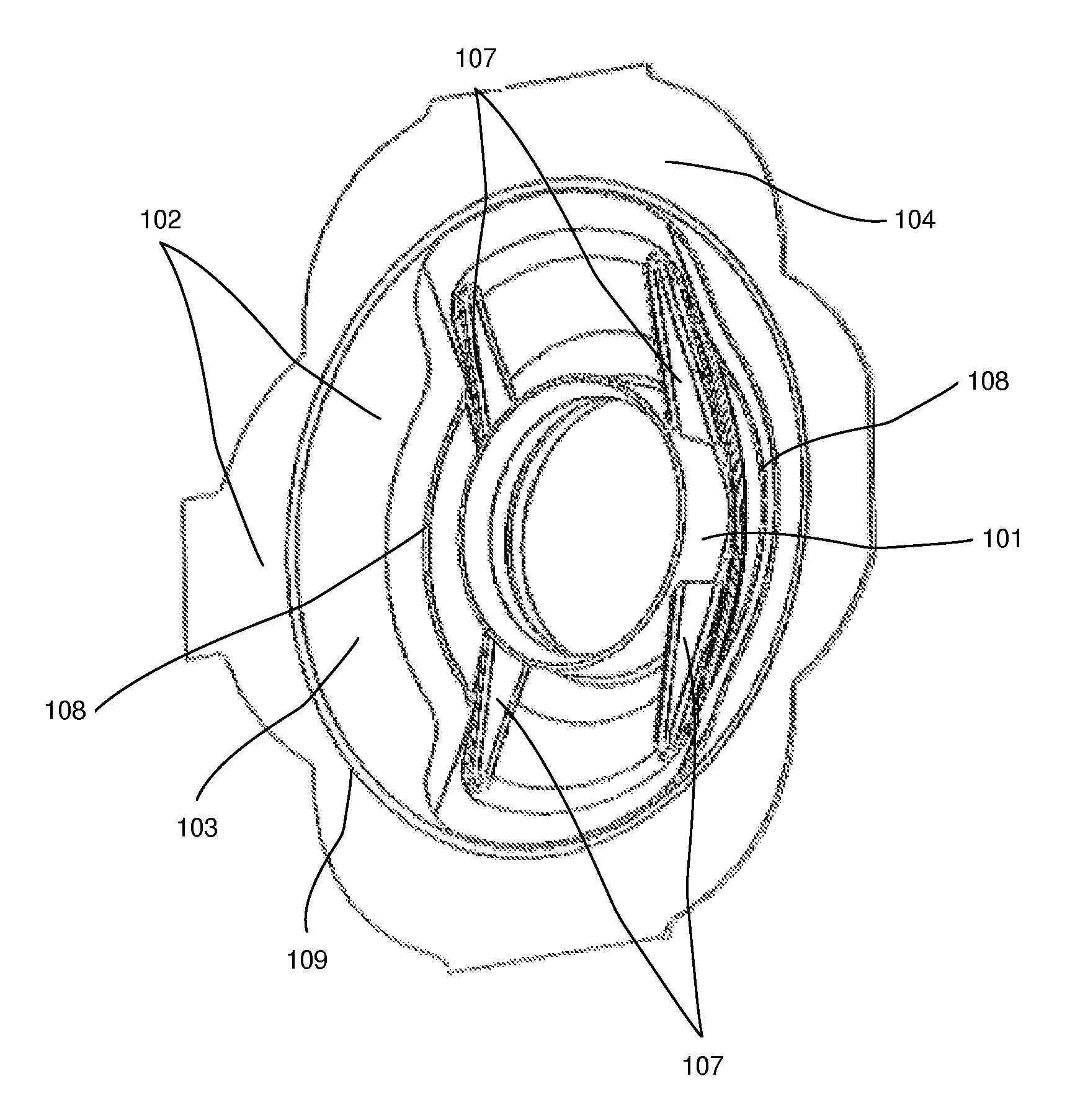
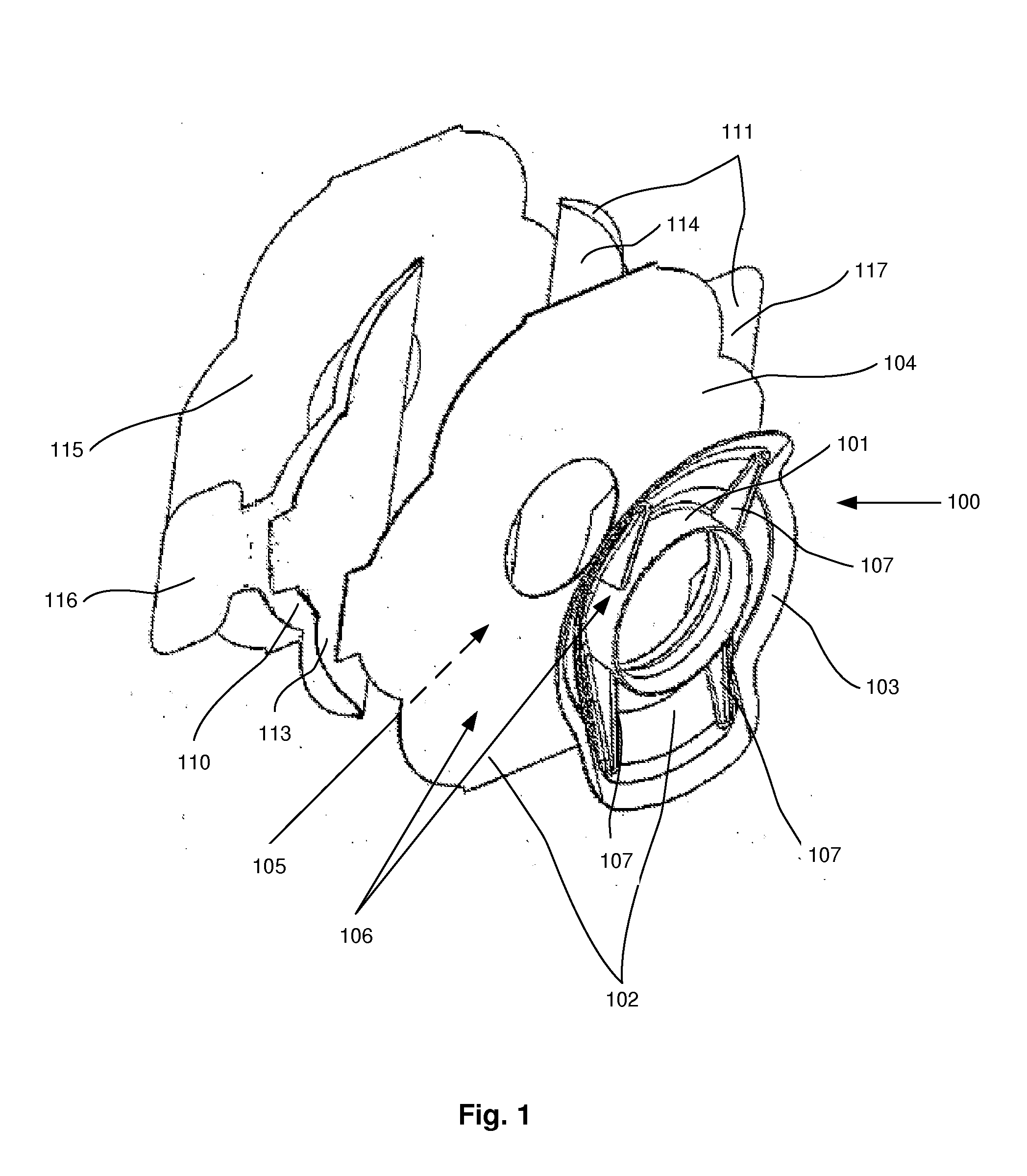
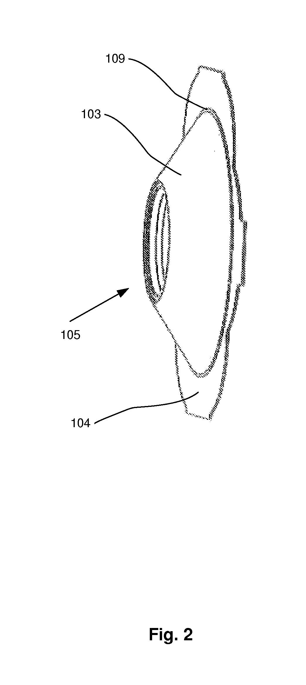
[0022]According to a first embodiment, disclosed as an exploded view in FIG. 1, a device 100 for holding a tracheostoma device, such as a HME, speech valve, etc, i.e. a tracheostoma device holder, is provided. The device comprises a tubular portion 101 for receiving the tracheostoma device in the distal end thereof. The tubular portion 101 may be of a circular cross-section, in a plane perpendicular to the central axis of the tubular portion 101. In the proximal end of the tubular portion 101 a flange 102 is provided, around the proximal opening of the tubular portion 101. The flange 102 comprises an inner rigid portion 103 and an outer more flexible portion 104. The flange 102 extends radially outwards from a proximal part of the tubular portion 101, in a plane perpendicular to the central axis of the tubular por...


PUM


Abstract

A device for holding a tracheostoma device over a tracheostoma of a patient including a passage having a distal and a proximal opening for receiving the tracheostoma device at the distal opening thereof. A flange may extend laterally, caudially, and cranially from the passage. The flange may have a proximal side facing the tracheostoma of the patient and a distal side facing outwardly from the patient. At least a part of said proximal side may include skin adhesive. The flange may have a higher moment of resistance in the caudal/cranial direction than in the lateral/medial direction for said device by having a higher moment of resistance in the caudal/cranial direction than in the lateral/medial direction for at least a part of said flange.

Description

FIELD OF THE INVENTION[0001]This invention pertains in general to the field of a device for holding a tracheostoma device and a method for applying such a device. More particular the invention pertains to a device for holding a tracheostoma device over a tracheostoma of a patient, said device comprising a tubular portion, having a distal and a proximal opening, for receiving the tracheostoma device in the distal opening thereof; a flange, extending laterally, caudially, and cranially from the tubular portion at a proximal part of the tubular portion, said flange having a proximal side, intended to face the tracheostoma of the patient, and a distal side, intended to face outwardly from the patient, at least a part of said proximal side being skin adhesive.BACKGROUND OF THE INVENTION[0002]A tracheostomy is a surgical procedure in which an opening is formed through the anterior surface of the neck into the trachea. The opening is referred to as a tracheostoma. A tracheostomy tube can b...

Claims


Application Information

Patent Timeline
IPC IPC(8): A61M16/04
CPCA61M16/0468A61M16/1045A61M16/047
Inventor PERSSON, JAN-OVE
Owner COLOPLAST AS
Why Eureka
Try Eureka