Weld electrical and gas connector with sealed gas flow

a gas flow and gas connector technology, applied in the field of welding systems, can solve problems such as the difficulty of managing multiple cables

Active Publication Date: 2011-10-13
ILLINOIS TOOL WORKS INC
View PDF10 Cites 25 Cited by
  • Summary
  • Abstract
  • Description
  • Claims
  • Application Information

AI Technical Summary

Benefits of technology

[0005]In an exemplary embodiment, a welding cable connector system includes a male connector having a first conductive body for conveying welding power. The male connector includes a first sealed passageway disposed coaxially of the first conductive body for conveying shielding gas, and a first gas sealing valve configured to seat to stop flow of shielding gas when the male connector is not engaged. The cable connector system also includes a female connector having a second conductive body for conveying welding power. The female connector includes a second sealed passageway disposed coaxially of the conductive body for conveying shielding gas, and a second gas sealing valve configured to seat to stop flow of shielding gas when the female connector is not engaged. The male and female connectors are mutually engageable to conduct welding power and shielding gas therethrough. The first and second gas sealing valves seal the flow of shielding gas when the connectors are not mutually engaged.

Problems solved by technology

Unfortunately, multiple cables can become hard to manage when many cables are required for each welding system.

Method used


Image

  • Weld electrical and gas connector with sealed gas flow
  • Weld electrical and gas connector with sealed gas flow
  • Weld electrical and gas connector with sealed gas flow

Examples


Embodiment Construction

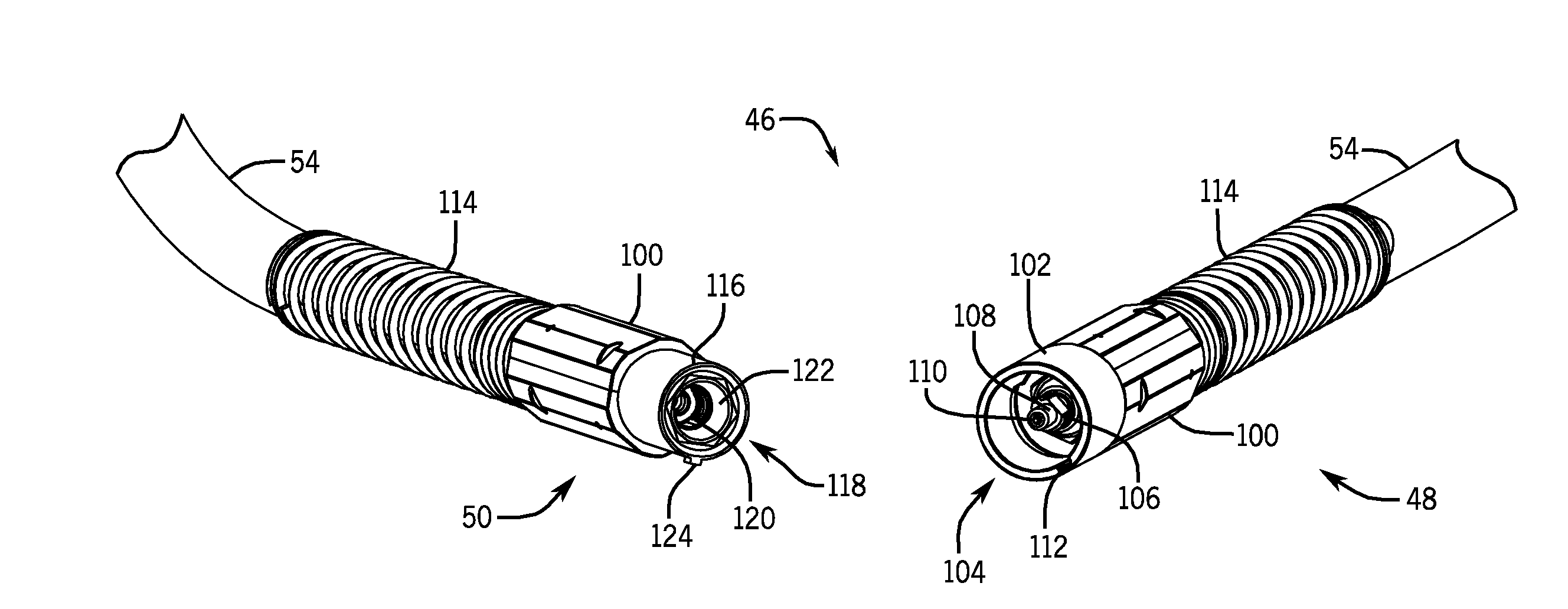
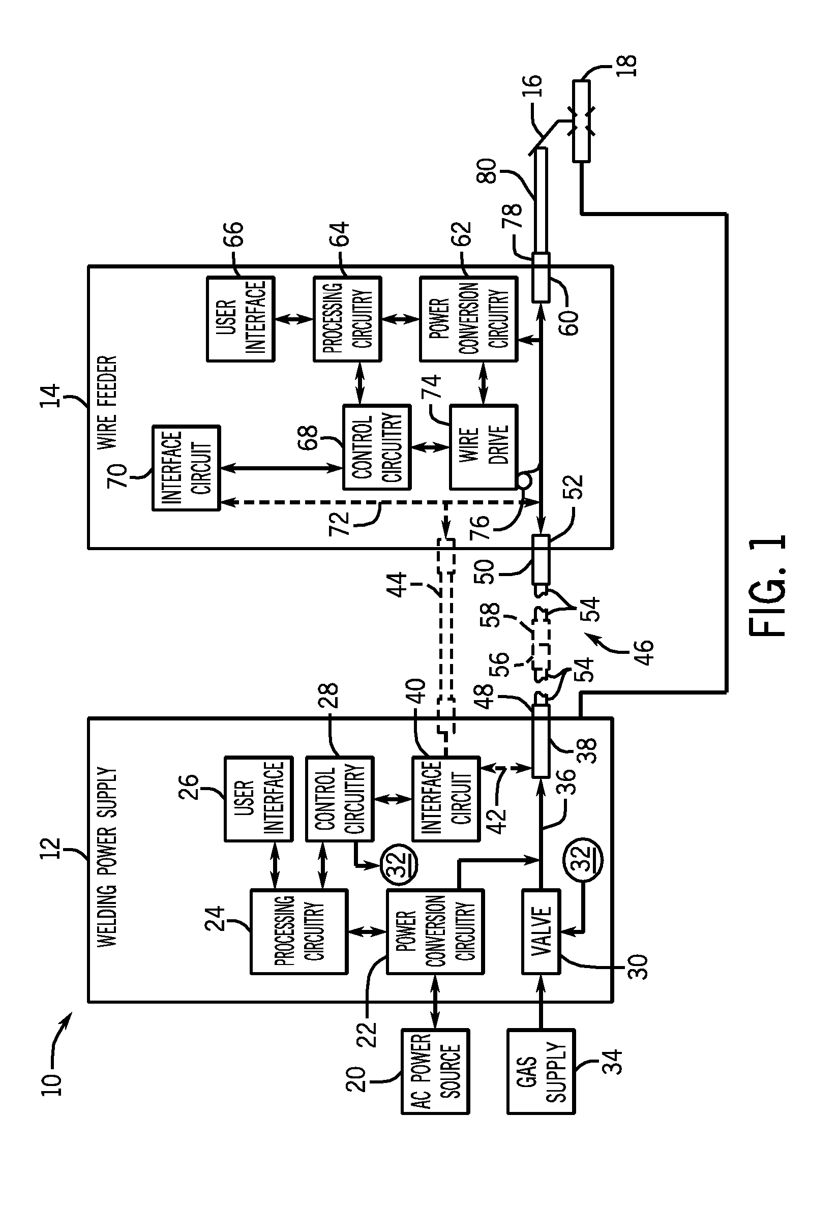
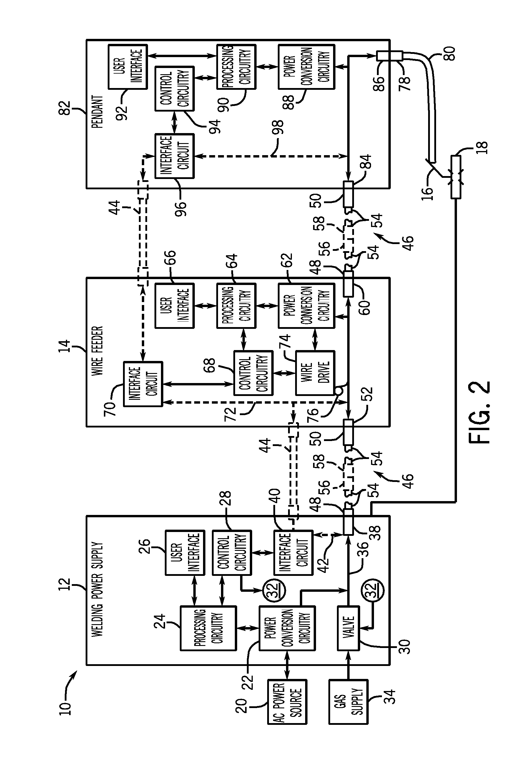
[0016]As described in detail below, embodiments of a weld electrical and gas connector with sealed gas flow are provided that may enable decreased number of cables in a welding system. For example, in certain embodiments gas and power are provided in a single cable, while in other embodiments gas, power, and control signals are provided in a single cable. Specifically, in one embodiment a welding cable connector system includes a male connector having a first conductive body for conveying welding power. The male connector includes a first sealed passageway disposed coaxially of the first conductive body for conveying shielding gas, and a first gas sealing valve configured to seat to stop flow of shielding gas when the male connector is not engaged. The cable connector system also includes a female connector having a second conductive body for conveying welding power. The female connector includes a second sealed passageway disposed coaxially of the conductive body for conveying shie...


PUM

PropertyMeasurementUnit
radiusaaaaaaaaaa
conductiveaaaaaaaaaa
electrical conductivityaaaaaaaaaa

Abstract

A weld electrical and gas connector with sealed gas flow is provided. In an exemplary embodiment, a welding cable connector system includes a male connector having a conductive body for conveying welding power. The male connector includes a sealed passageway disposed coaxially of the conductive body for conveying shielding gas, and a gas sealing valve configured to seat to stop flow of shielding gas when the male connector is not engaged. The system also includes a female connector having a conductive body for conveying welding power. The female connector includes a sealed passageway disposed coaxially of the conductive body for conveying shielding gas, and a gas sealing valve configured to seat to stop flow of shielding gas when the female connector is not engaged. The male and female connectors are mutually engageable to conduct welding power and shielding gas therethrough.

Description

CROSS REFERENCE TO RELATED APPLICATIONS[0001]This application is a Non-Provisional Patent Application of U.S. Provisional Patent Application No. 61 / 323,704 entitled “Weld Connector With Sealed Gas Flow”, filed Apr. 13, 2010, which is herein incorporated by reference.BACKGROUND[0002]The invention relates generally to welding systems and, more particularly, to a weld electrical and gas connector with sealed gas flow.[0003]Welding is a process that has become increasingly ubiquitous in various industries and applications. While such processes may be automated in certain contexts, a large number of applications continue to exist for manual welding operations. Such welding operations rely on a variety of types of equipment to ensure the supply of welding consumables (e.g., wire feed, shielding gas, etc.) is provided to the weld in an appropriate amount at the desired time. For example, metal inert gas (MIG) welding typically relies on a wire feeder to ensure a proper wire feed reaches a ...

Claims


Application Information

Patent Timeline
Patent Type & Authority Applications(United States)
IPC IPC(8): B23K9/16
CPCB23K9/323B23K9/173
Inventor IHDE, JEFFERY RAYLAHTI, THOMAS DONRAPPL, JAMES FRANCISFELDHAUSEN, JOSEPH EDWARD
Owner ILLINOIS TOOL WORKS INC
Why Eureka
Try Eureka