Welding gas leak detection system and method

a detection system and gas leak technology, applied in the field of welding systems, can solve the problems of shielding gas exiting the welding system at an undesired location, insufficient quantity of shielding gas, and waste of shielding gas

Active Publication Date: 2011-11-24
ILLINOIS TOOL WORKS INC
View PDF4 Cites 36 Cited by
  • Summary
  • Abstract
  • Description
  • Claims
  • Application Information

AI Technical Summary

Benefits of technology

[0006]In an exemplary embodiment, a welding power supply includes a gas valve configured to control the flow of shielding gas to a welding device through a gas line. The welding power supply also includes a sensor coupled to the gas line and configured to detect a parameter of the shielding gas. The welding power supply includes control circuitry coupled to the gas valve and to the sensor, and configured to control the operation of the gas valve, and to receive a value representative of the detected parameter. The control circuitry is further configured to determine a leak test result based upon the parameter value, and to provide an operator indicator of the leak test result.
[0007]In another embodiment, a welding system includes a welding power supply having a gas valve, a first sensor, and control circuitry. The control circuitry is configured to control the gas valve to control the flow of shielding gas to a welding application through a gas line. The first sensor is coupled to the gas line and configured to detect a first parameter of the shielding gas. The welding system also includes a welding component coupled to the gas line between the first sensor and the welding application, and having a second sensor configured to detect a second parameter of the shielding gas. Monitoring circuitry configured to receive first and second values representative of the first and second parameters, to determine a leak test result based upon the parameter values, and to provide an operator indicator of the leak test result.

Problems solved by technology

Unfortunately, the gas hoses and cables or connections between them may develop leaks which cause the shielding gas to exit the welding system at an undesired location.
Thus, shielding gas may be wasted and an insufficient quantity of shielding gas may reach the welding torch.
Furthermore, environmental air may enter the gas cables and act as a contaminant that may adversely affect the weld.

Method used


Image

  • Welding gas leak detection system and method
  • Welding gas leak detection system and method
  • Welding gas leak detection system and method

Examples


Embodiment Construction

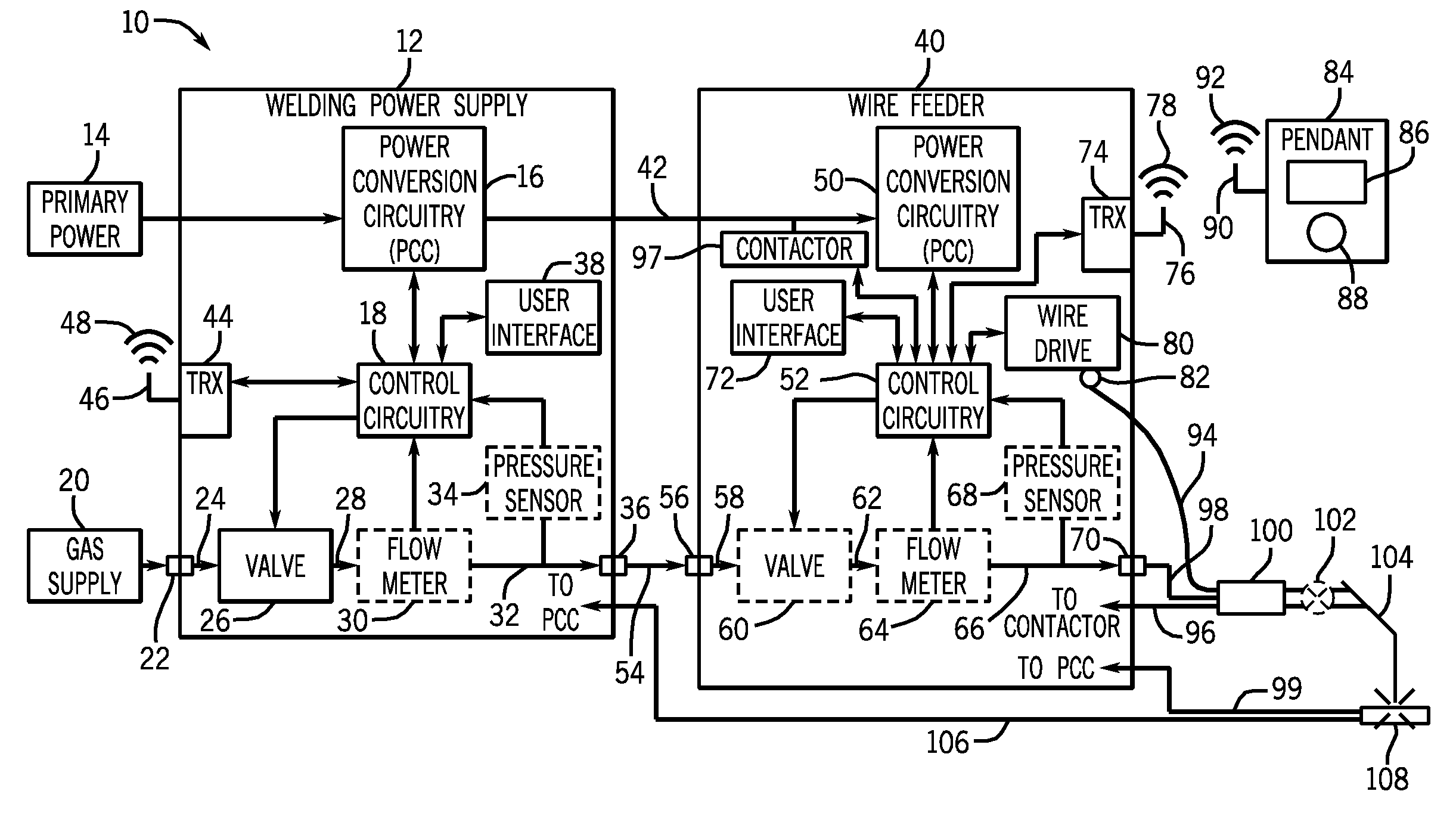
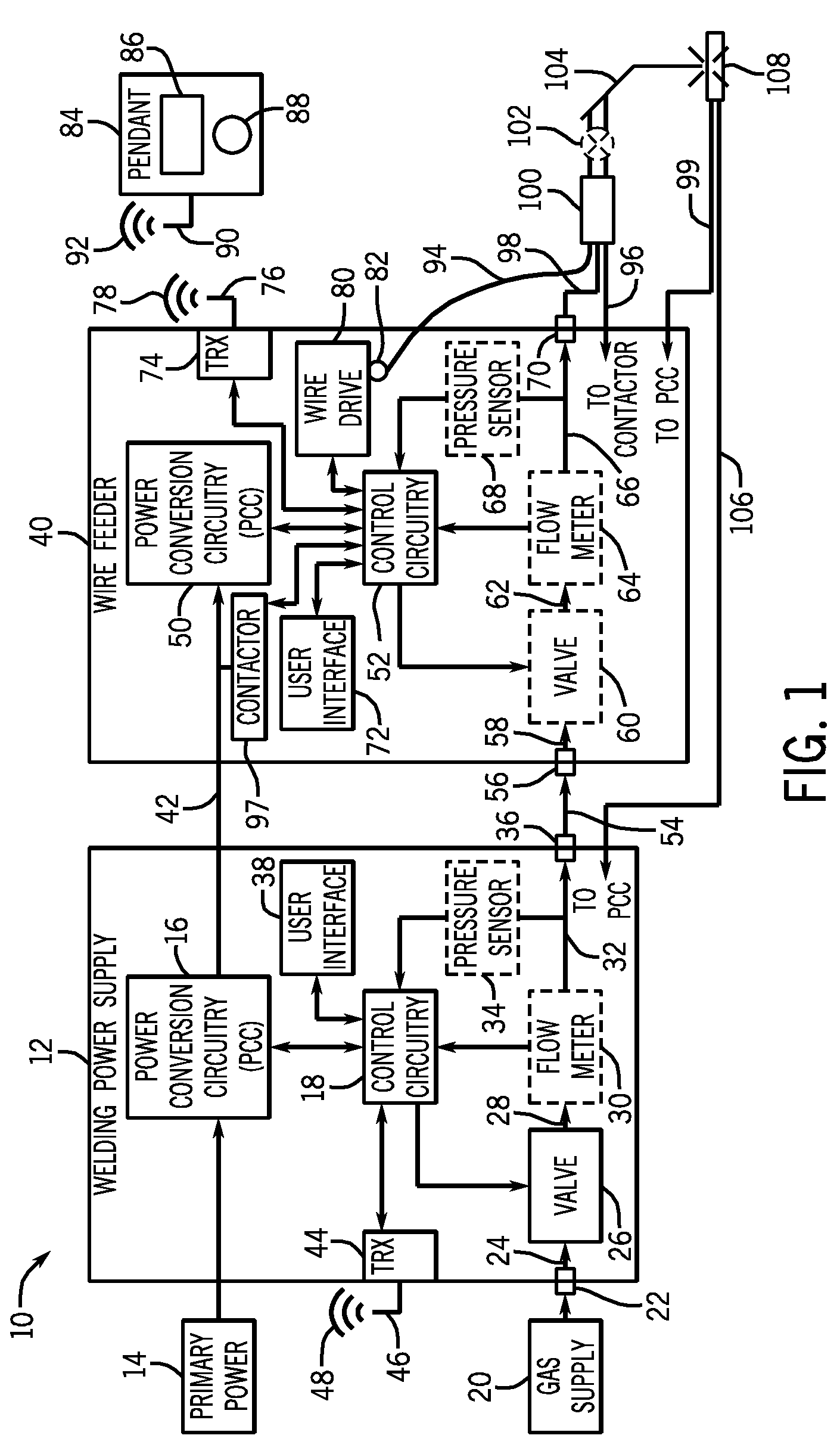
[0017]Turning now to the drawings, FIG. 1 is a schematic diagram of an embodiment of a welding system 10 with a gas leak detection system. In the illustrated embodiment, the welding system is a MIG welding system, although the present techniques may be used on other welding systems utilizing compressed gases, such as tungsten inert gas (TIG) systems, and so forth. The welding system 10 powers, controls, and supplies consumables to a welding application. The welding system 10 includes a welding power supply 12.

[0018]The welding power supply 12 receives primary power 14 (e.g., from the AC power grid, an engine / generator set, a battery, or other energy generating or storage devices, or a combination thereof), conditions the primary power, and provides an output power to one or more welding devices in accordance with demands of the system 10. The primary power 14 may be supplied from an offsite location (i.e., the primary power may originate from the power grid). Accordingly, the weldin...


PUM

PropertyMeasurementUnit
of timeaaaaaaaaaa
pressure parameteraaaaaaaaaa
pressureaaaaaaaaaa

Abstract

A method and system for detecting a welding gas leak is provided. One welding power supply includes a gas valve configured to control the flow of shielding gas to a welding device through a gas line. The welding power supply also includes a sensor coupled to the gas line and configured to detect a parameter of the shielding gas. The welding power supply includes control circuitry coupled to the gas valve and to the sensor, and configured to control the operation of the gas valve, and to receive device value representative of the detected parameter. The control circuitry is further configured to determine a leak test result based upon the parameter value, and to provide an operator indicator of the leak test result.

Description

CROSS REFERENCE TO RELATED APPLICATIONS[0001]This application is a Non-Provisional Patent Application of U.S. Provisional Patent Application No. 61 / 347,084 entitled “Welding Shielding Gas Leak Detection”, filed May 21, 2010, which is herein incorporated by reference.BACKGROUND[0002]The invention relates generally to welding systems and, more particularly, to a welding gas leak detection system and method.[0003]Welding is a process that has increasingly become ubiquitous in various industries and applications. Such processes may be automated in certain contexts, although a large number of applications continue to exist for manual welding operations. In both cases, such welding operations rely on a variety of types of equipment to ensure the supply of welding consumables (e.g., wire feed, shielding gas, etc.) is provided to the weld in an appropriate amount at the desired time. For example, metal inert gas (MIG) welding typically relies on the integrity of shielding gas cables to enab...

Claims


Application Information

Patent Timeline
Patent Type & Authority Applications(United States)
IPC IPC(8): B23K9/16
CPCB23K9/1006G01M3/2815F17D5/06B23K9/164
Inventor RAPPL, JAMES FRANCISLAHTI, THOMAS DONIHDE, JEFFERY RAY
Owner ILLINOIS TOOL WORKS INC
Why Eureka
Try Eureka