Cushion Mat with Pressure Sensor

a technology of pressure sensor and cushion mat, which is applied in the field of cushion mat, can solve the problems of occupant detection system, complicated mechanical arrangement, and totally different seat construction, and achieve the effect of cost saving and no negative effect on the cushioning behavior of the cushion ma

Active Publication Date: 2011-10-13
FICO CABLES LDA (PT)
View PDF3 Cites 24 Cited by
  • Summary
  • Abstract
  • Description
  • Claims
  • Application Information

AI Technical Summary

Benefits of technology

[0016]On the other hand the pressure sensor can also be arranged at an assembly area that is arranged at an area of lowest load of the cushion mat. This ensures, that a seat occupation signal is also provided, if the passenger does not take the optimal position on the seat. In such a case, the pressure sensor signal is more reliable despite different passenger positions.
[0017]In a preferred embodiment the pressure sensor is

Problems solved by technology

Such occupant detection systems have the disadvantage that they require totally different seat constructions, complicated mechanical arrangements or require additional mounting steps for the force

Method used


Image

  • Cushion Mat with Pressure Sensor
  • Cushion Mat with Pressure Sensor
  • Cushion Mat with Pressure Sensor

Examples


Embodiment Construction

[0035]In the following preferred embodiments of the present invention are described in detail with respect to the drawings.

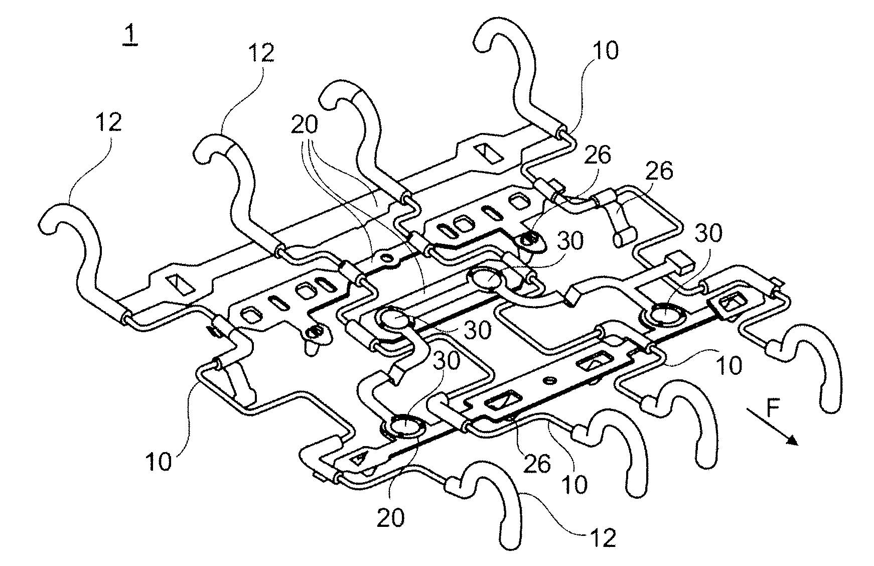
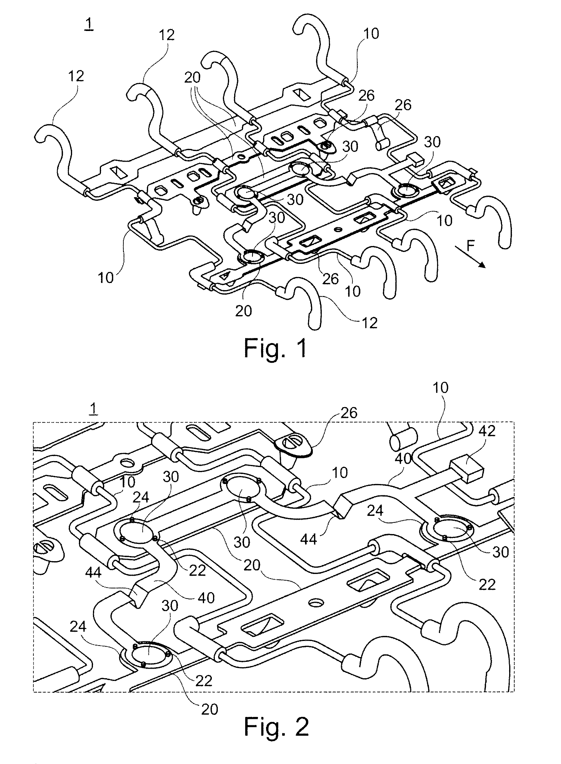
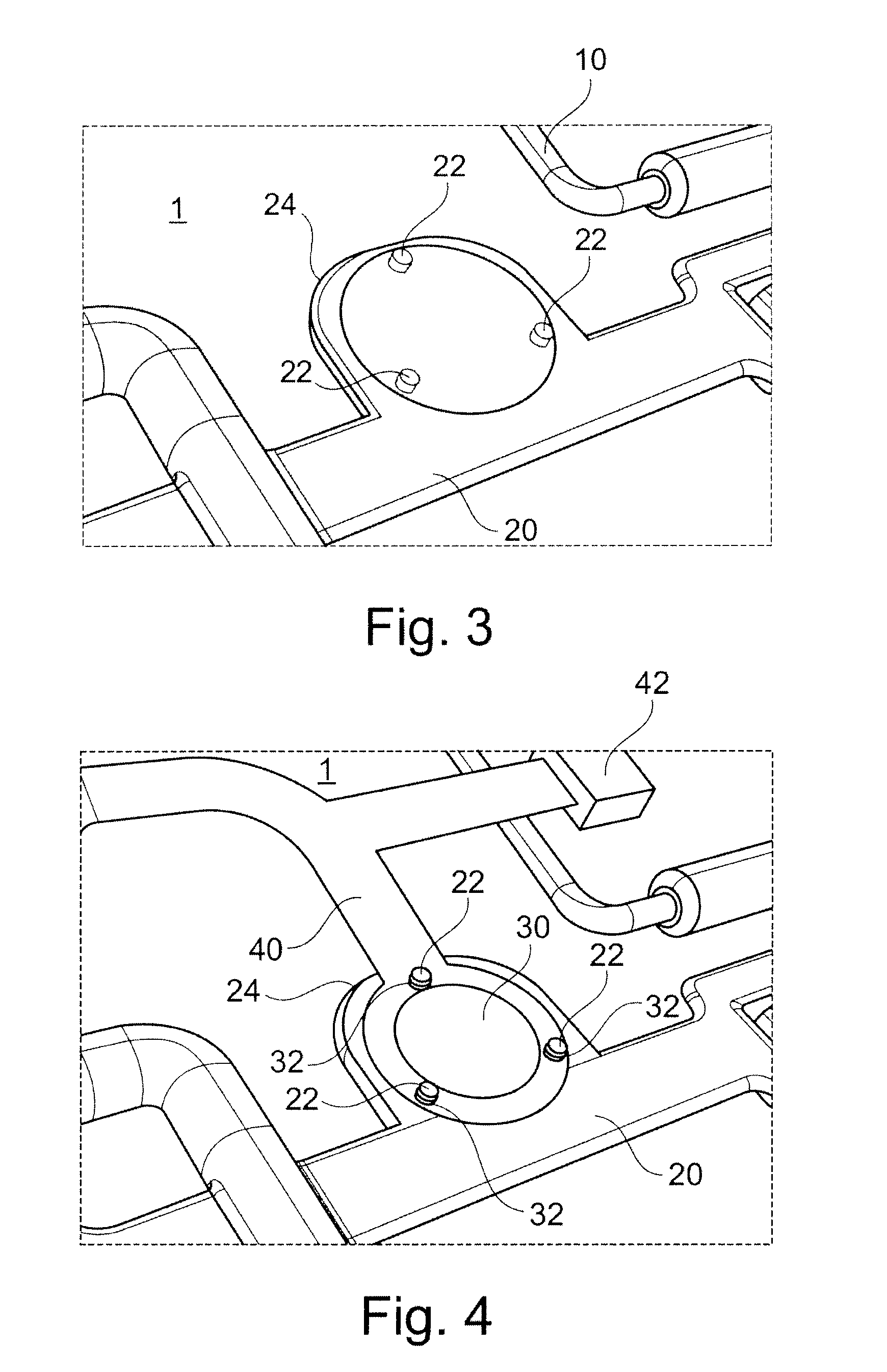
[0036]FIG. 1 shows a three-dimensional view of a cushion mat 1 according to the invention. The cushion mat 1 comprises four metal wire springs 10 which are bent in a staggered fashion to provide elasticity. Plastic connectors 20 which are injection overmolded over the set of metal wire springs 10 interconnect the wire springs 10 with each other to form the basic structure of the cushion mat 1. As illustrated in FIG. 1 the plastic connectors 20 may have almost any arbitrary shape and are generally designed as flat plastic bands in between the wire springs 10. The plastic connectors 20 surround the wire springs 10 by tube shaped portions.

[0037]The design and the position of the plastic connectors 20 together with the elasticity of the metal wire springs 10 define the support behavior of the cushion mat 1. Therefore, the cushion mats 1 my have different support beh...


PUM

PropertyMeasurementUnit
Weightaaaaaaaaaa
Flexibilityaaaaaaaaaa
Areaaaaaaaaaaa

Abstract

The present invention relates to a cushion mat 1 for integration into an automotive seat, comprising a set of metal wire springs 10, plastic connectors 20, connecting the wire springs 10 with each other to form a cushion mat 1, and at least one pressure sensor 30 directly connected to one of the plastic connectors 20 for providing a seat occupation signal. Further a method for the production of cushion mats 1 for integration into an automotive seat is disclosed, comprising the following steps (a) injection molding of plastic material around a set of metal wire springs 10 to form a cushion mat 1 with plastic connectors 20, wherein the plastic connectors 20 having at least one assembly area 24 for a pressure sensor 30, (b) arranging at least one pressure sensor 30 at the assembly area 24, and (c) connecting the pressure sensor 30 at the assembly area 24.

Description

STATEMENT OF RELATED CASES[0001]Pursuant to 35 U.S.C. 119(a), the instant application claims priority to prior European application number 10 159 502.3, filed Apr. 9, 2010. This application also claims the benefit of U.S. Provisional Application No. 61 / 350,686, filed Jun. 2, 2010.FIELD OF THE INVENTION[0002]The present invention relates to a cushion mat for the integration into an automotive seat. Such cushion mats are generally known in the prior art and are used in the seat and the back rest of a motor vehicle seat and act for the suspension of the cushioning.PRIOR ART[0003]Cushioning mats made of metal wires are known in the prior art which carry the cushioning of a seat or of a back rest of a motor vehicle seat. Such cushioning mats are usually hinged into a metal seat frame of the motor vehicle seat. Usually, the cushioning mat consists of specially formed metal wires which are connected to each other by appropriate means to provide a suspension respectively a cushioning effect...

Claims


Application Information

Patent Timeline
IPC IPC(8): B60N2/44G01D7/00B29C65/02B60R21/015B60N2/90
CPCB60N2/7094B60N2/002
Inventor PINTO RIBEIRO, SUSANA CARLA
Owner FICO CABLES LDA (PT)
Why Eureka
Try Eureka