
System and method for magnetometer installation

a magnetometer and installation system technology, applied in the field of system and method for magnetometer installation, can solve the problem of difficult to know the extent of interfering extraneous magnetic fields for a particular location on the aircraft, and achieve the effect of facilitating the location of any ferrous material and facilitating the determination

Active Publication Date: 2011-10-13
L3 AVIATION PROD INC
View PDF12 Cites 1 Cited by
  • Summary
  • Abstract
  • Description
  • Claims
  • Application Information

AI Technical Summary

Benefits of technology

[0004]According to one aspect, a system and method are provided for assisting in the determination of a suitable location in or on a mobile craft for mounting one or more magnetometers. In one aspect, the system facilitates determining whether or not electrical or other powered subsystems onboard the aircraft will unduly interfere with the operation of the magnetometer. In another aspect, the system facilitates location of any ferrous material or magnetic interference that is present in an area of the craft.
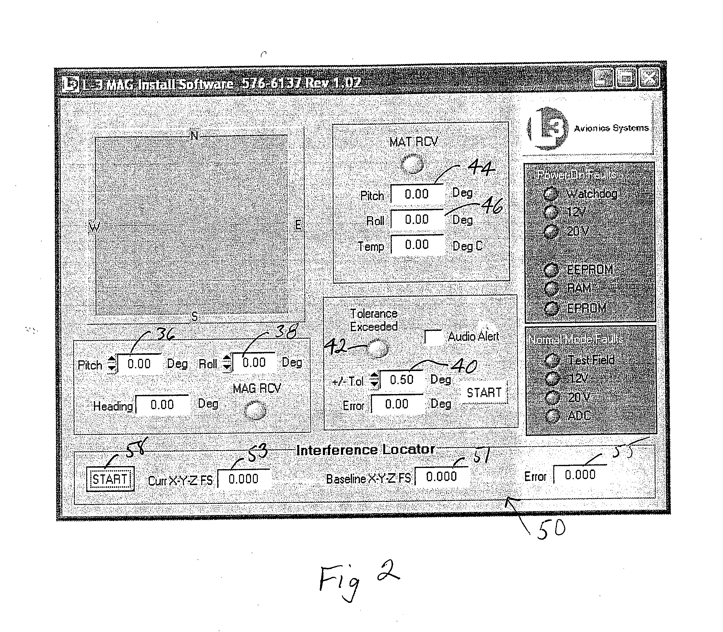
[0011]The powered component may be the engine of the aircraft, an electrically operated subsystem or component, or any other part of the aircraft that may cause magnetic interference when operated. By having a computer automatically monitor the output of the magnetometer while one or more powered components of the aircraft are operated, any undue changes to the magnetometer heading may automatically be detected without requiring a technician or other person to physically monitor the magnetometer output as those powered components are operated. Thus, the method and system facilitate determining whether any onboard powered components of the aircraft will unduly interfere with the operation of the magnetometer. In at least one aspect, the specified amount may be chosen by a technician or other personnel and entered into the computer. In this manner, the tolerance level of an acceptable amount of magnetic interference may be chosen.

Problems solved by technology

In many cases, however, it is difficult to know the extent of any interfering extraneous magnetic fields for a particular location on the aircraft.

Method used


Image

  • System and method for magnetometer installation
  • System and method for magnetometer installation
  • System and method for magnetometer installation

Examples


Embodiment Construction

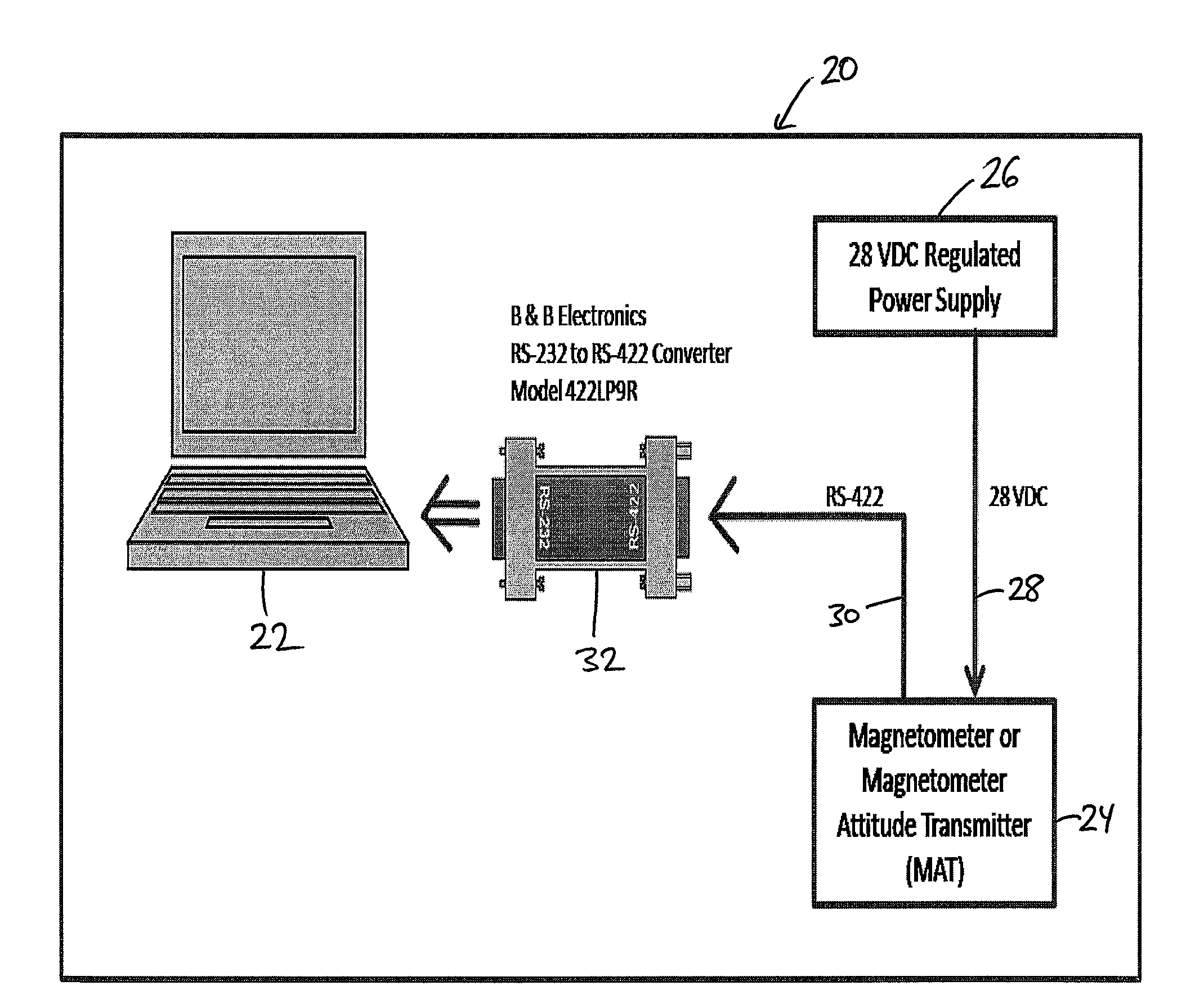
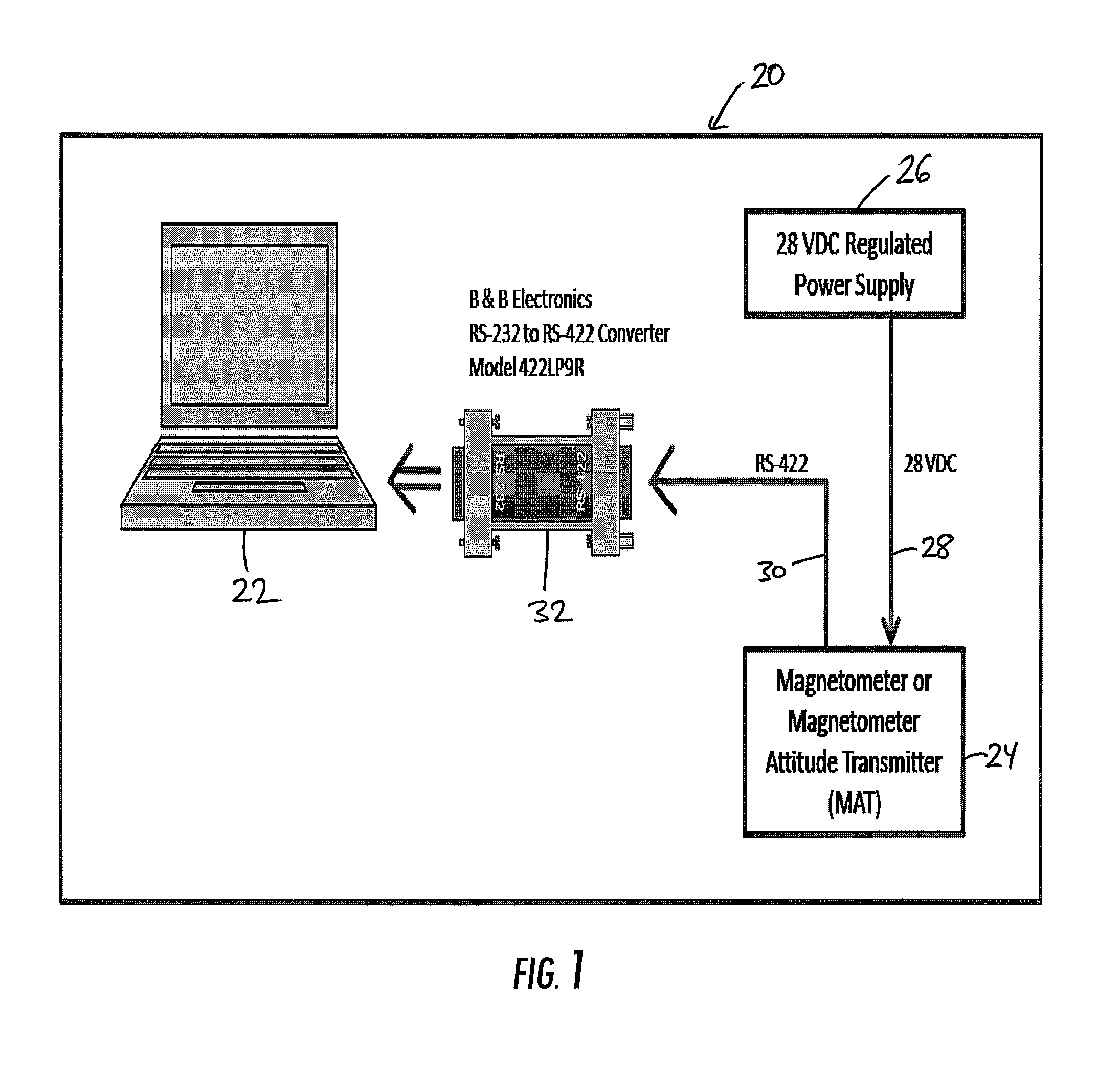
[0016]Referring now to the drawings and the illustrative embodiments depicted therein, a magnetometer assessment system 20 according to one embodiment is shown in diagram form in FIG. 1. The magnetometer assessment system includes a computer 22, a magnetometer 24, a power supply 26, a power cable 28, at least one data cable 30, and an optional converter 32. System 20 operates after magnetometer 24 has been installed into an intended location on a mobile craft. While system 20 has applicability to multiple different types of mobile crafts in which a magnetometer may be mounted, it will be assumed for purposes of the following discussion that the mobile craft is an aircraft. This assumption, however, should not be interpreted to limit the applicability of system 20 to other types of mobile crafts.

[0017]System 20 is especially adapted to determine the suitability of mounting magnetometer 24 in a particular location of an aircraft as part of an aftermarket installation of the magnetomet...


PUM


Abstract

A method and system for determining the suitability of a particular location on a mobile craft for mounting a magnetometer includes positioning a magnetometer in a particular location. The magnetometer including at least one output indicating magnetic measurements made by the magnetometer. A computer is connected to the magnetometer and programmed to monitor the output(s) of the magnetometer. An attempt is made to detect magnetic interference at the mobile craft and a human-perceptible indication is provided if the output(s) of said magnetometer changes by more than a specified amount while attempting to detect magnetic interference.

Description

CROSS-REFERENCE TO RELATED APPLICATION[0001]This application claims priority from U.S. provisional patent application Ser. No. 61 / 321,754, filed on Apr. 7, 2010, the disclosure of which is hereby incorporated herein by reference in its entirety.BACKGROUND OF THE INVENTION[0002]The present invention relates to a system and method for installing one or more magnetometers on a mobile craft, such as, but not limited to, an aircraft.[0003]When installing a magnetometer in an airplane, it is important that the installer chooses a location in the airplane that is substantially free of magnetic interference, whether from ferrous materials, high-current cables, or any current-carrying wires that are unshielded. Locations, such as baggage compartment areas, avionics bays, wings, and near landing gears are often avoided. In many cases, however, it is difficult to know the extent of any interfering extraneous magnetic fields for a particular location on the aircraft.SUMMARY OF THE INVENTION[000...

Claims


Application Information

Patent Timeline
Patent Type & Authority Applications(United States)
IPC IPC(8): G08B17/12
CPCG01C17/38G01R33/022G01R33/007
Inventor TRAMPER, WILLIAM D.DEROSIA, ANDREW L.
Owner L3 AVIATION PROD INC
Learn More