Autostereoscopic display device

a display device and autostereoscopic technology, applied in the field of autostereoscopic display devices, can solve problems such as non-homogeneity in perception, and achieve the effect of further improving the display that uses the slanting of the lenticular

Active Publication Date: 2011-10-13
KONINKLIJKE PHILIPS ELECTRONICS NV
View PDF0 Cites 20 Cited by
  • Summary
  • Abstract
  • Description
  • Claims
  • Application Information

AI Technical Summary

Benefits of technology

[0007]The present invention is based on the recognition that a display that uses slanting of the lenticular may be further improved. The improvement is related to the fact that slanting may result in an irregular pixel distribution of pixels (or colour sub-pixels) which make up the individual views. This arises because the pattern of the pixels or sub-pixels from the 2D image is imaged by the lens arrangement to the individual viewing locations. The relative slant between the lenses and the pixels means that the pixels (or sub-pixels) are not regularly arranged in an even grid. This results in perceptual non-homogeneity which may be perceived as an annoying effect by a viewer.
[0014]This arrangement enables that the resulting image projected in respect of each view to have a uniform and regular distribution of pixels across the image. This improves the visual appearance of the views.

Problems solved by technology

This results in perceptual non-homogeneity which may be perceived as an annoying effect by a viewer.

Method used


Image

  • Autostereoscopic display device
  • Autostereoscopic display device
  • Autostereoscopic display device

Examples


Embodiment Construction

[0046]The invention will be described according to exemplifying embodiments with reference to the drawings.

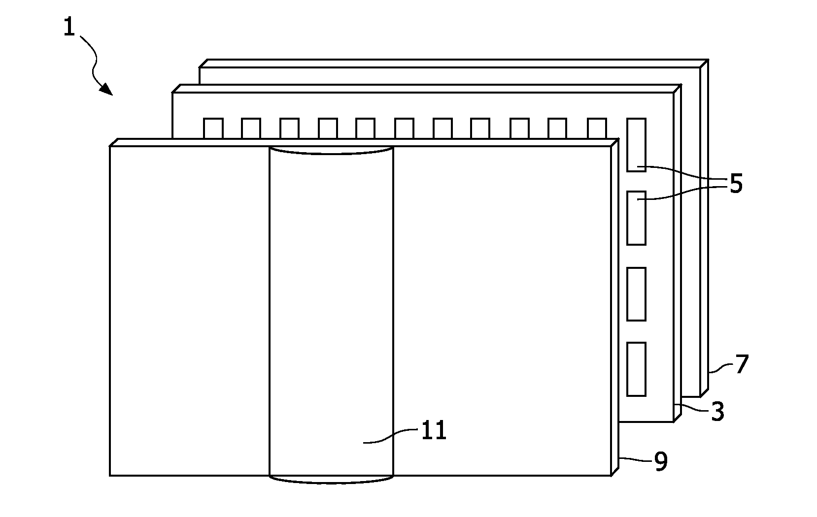
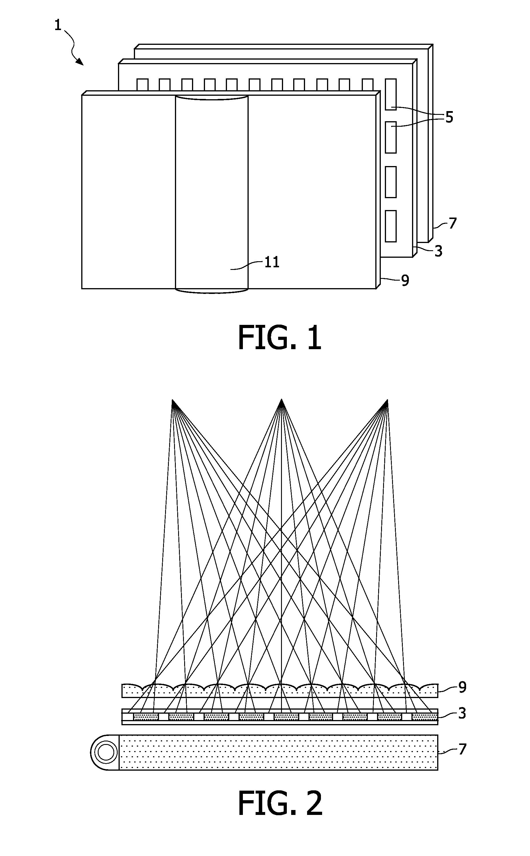
[0047]FIG. 1 is a schematic perspective view of a multi-view autostereoscopic display device 1. The device 1 comprises a liquid crystal display panel 3 of the active matrix type that acts as an image forming means to produce the display.

[0048]The display panel 3 has an orthogonal array of display pixels 5 arranged in rows and columns in a surface that in this case is planar. For the sake of clarity, only a small number of display pixels 5 are shown in FIG. 1. In practice, the display panel 3 might comprise about one thousand rows and several thousand columns of display pixels 5.

[0049]The structure of the liquid crystal display panel 3 is entirely conventional. In particular, the panel 3 comprises a pair of spaced transparent glass substrates, between which an aligned twisted nematic or other liquid crystal material is provided. The substrates carry patterns of transparent indiu...


PUM


Abstract

An autostereoscopic display device comprises a display (103) having an array of display pixels (105) and a view forming arrangement (109) of elongate elements which have a long axis which is slanted at an angle α to the column pixel direction, and the elements have a pitch of P times the width between pixels of the same colour in different columns. The pitch P is selected to be: P=0.5·k·(1+S2) in which S=tan α, and k is a positive integer. This arrangement enables the resulting image projected in respect of each view to have a uniform and regular distribution of pixels across the image. This improves the visual appearance of the views.

Description

FIELD OF THE INVENTION[0001]This invention relates to an autostereoscopic display device with a display panel having an array of display pixels, and an arrangement for directing different views to different physical locations.BACKGROUND OF THE INVENTION[0002]A known autostereoscopic display device of the type of the previous paragraph is described in GB 2196166 A. This known device comprises a two dimensional emissive liquid crystal display panel having a row and column array of display pixels acting as an image forming means to produce a display. An array of elongate lenticular lenses extending parallel to one another overlies the display pixel array and acts as a view forming means. Outputs from the display pixels are projected through these lenticular lenses, which function to modify the directions of the outputs.[0003]The lenticular lenses are provided as a sheet of elements, each of which comprises an elongate semi-cylindrical lens element. The lenticular lenses extend in the c...

Claims


Application Information

Patent Timeline
Patent Type & Authority Applications(United States)
IPC IPC(8): G06T15/00G02B30/29G02B30/32
CPCH04N13/0404H04N13/0409G02B27/2214H04N13/0447G02B27/225H04N13/0415H04N13/305H04N13/31H04N13/317H04N13/351G02B30/32G02B30/29H04N13/00G02B30/27
Inventor VAN DER HORST, JANVAN DALFSEN, AGE JOCHEM
Owner KONINKLIJKE PHILIPS ELECTRONICS NV
Why Eureka
Try Eureka