Coupling lens, illuminating device, and electronic device

a technology of illuminating device and lens, applied in the field of illuminating device, can solve the problems of inability to achieve disadvantage in achieving small size and lightweight device, etc., to achieve the effect of improving light use efficiency, improving wave front quality of light flux, and small device siz

Active Publication Date: 2011-10-13
RICOH KK
View PDF9 Cites 23 Cited by
  • Summary
  • Abstract
  • Description
  • Claims
  • Application Information

AI Technical Summary

Benefits of technology

[0016]The present invention is mainly to provide an illuminating device for achieving a small size device and improvement of light use efficiency and for improving a wave front quality of light fluxes.

Problems solved by technology

In such a method of combining color light, the focusing lens is necessary for each laser so that the number of parts and components is increased and a small size and lightweight device cannot be achieved.
In such a configuration, although only one focusing lens is used, the light sources are arranged such that the emitting directions of the light sources are different from each other so that there is a disadvantage in achieving a small size and lightweight device.
Furthermore, the large size of the apparatus cannot be prevented because of the large focal length.
If the focal length of the collimating lens is set to be small, it is difficult to remove astigmatism generated in the light reflected on a rear surface of the two beam combining prism under practical conditions such as an interval between the two light sources, and thickness of the two beam combining prism.
Accordingly, it is difficult to combine light fluxes from the two light sources by one collimating lens of small focal length.
As described above, it is difficult, by use of one collimating lens of a small focal length, to combine light fluxes from a plurality of light sources with good wave front onto one light path via a two beam combining prism by allowing the two light sources to emit light fluxes in the substantially same directions and allowing one coupling lens to couple the light fluxes, as described in the conventional technology.

Method used


Image

  • Coupling lens, illuminating device, and electronic device
  • Coupling lens, illuminating device, and electronic device
  • Coupling lens, illuminating device, and electronic device

Examples


first embodiment

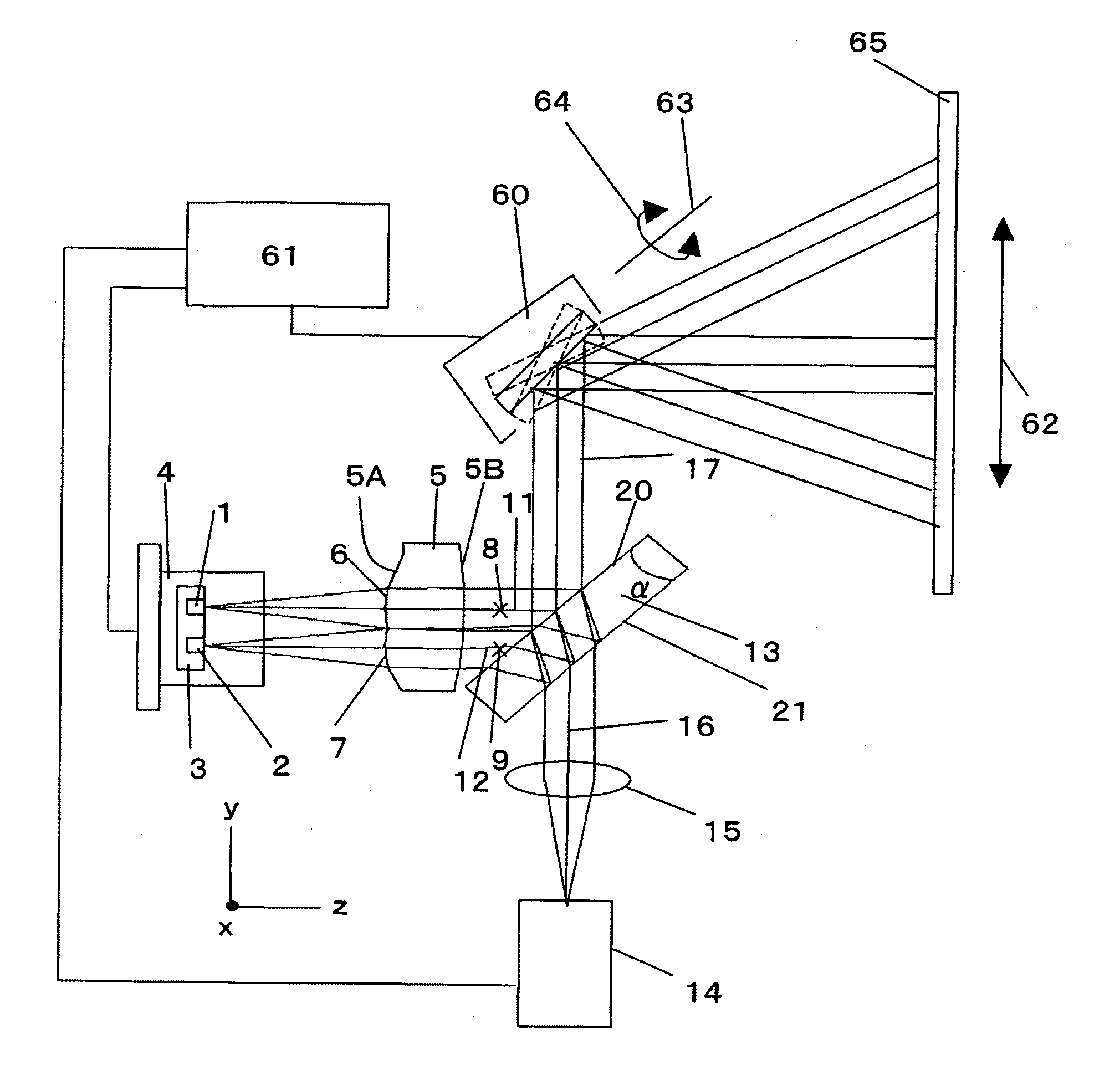
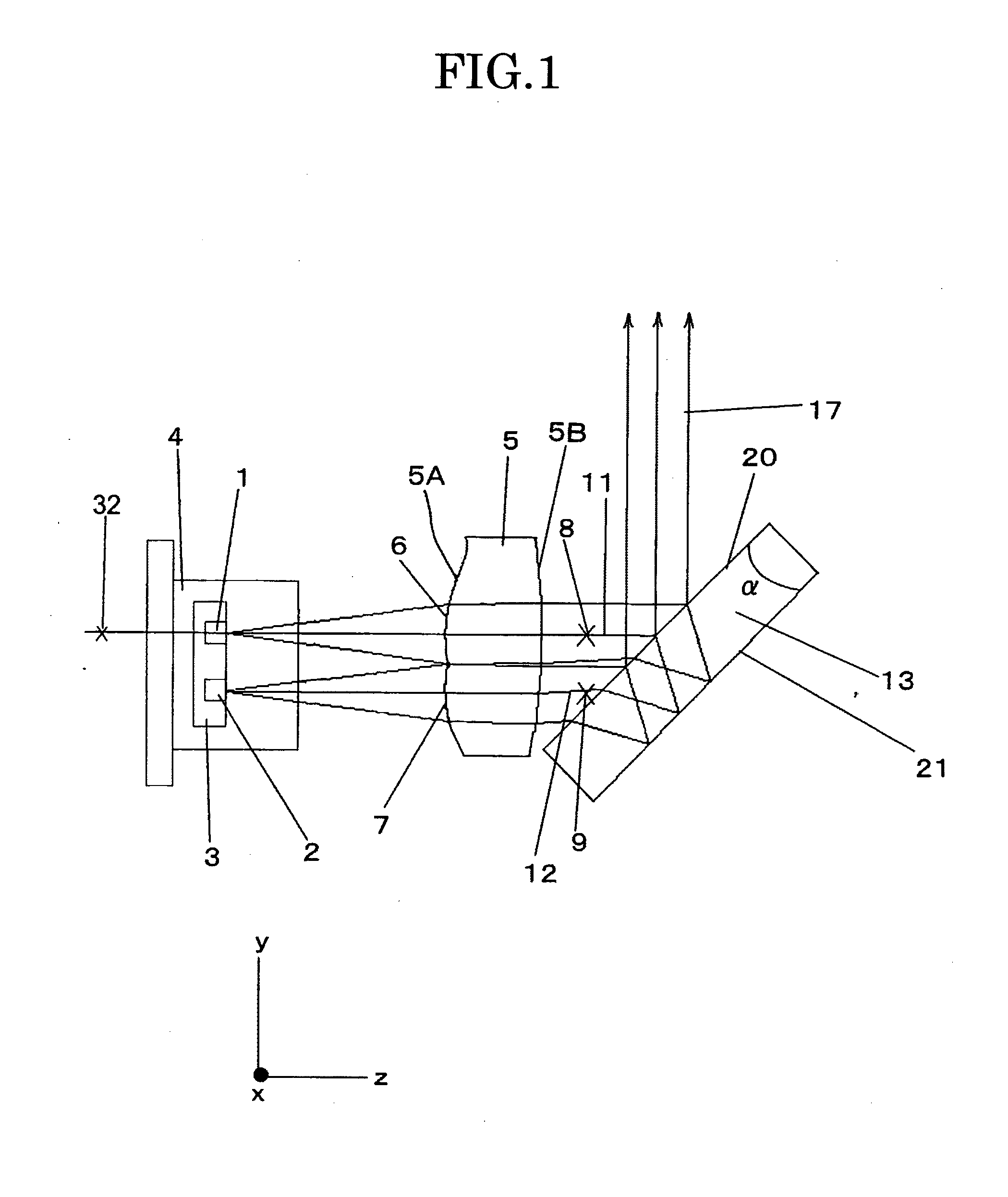
[0043]FIG. 1 shows an illuminating device having a coupling lens according to the present invention. The illuminating device includes a first light source 1 configured to emit first light having a first wavelength λ1, a second light source 2 disposed adjacent to the first light source 1 and configured to emit second light having a second wavelength λ2, and a coupling lens 5 configured to couple the first light with the second light. The first light and the second light are emitted in the substantially same direction. The coupling lens 5 has a first surface 5A facing the first and second light sources 1, 2 and a second surface 5B disposed at an opposite side of the first surface 5A and having a second-surface curvature. The first surface 5A includes a first region 6 through which the first light passes and a second region 7 through which the second light passes. The first region 6 has a first region curvature and the second region 7 has a second region curvature. A position of a firs...

second embodiment

[0070]the present invention will be explained with reference to FIG. 5.

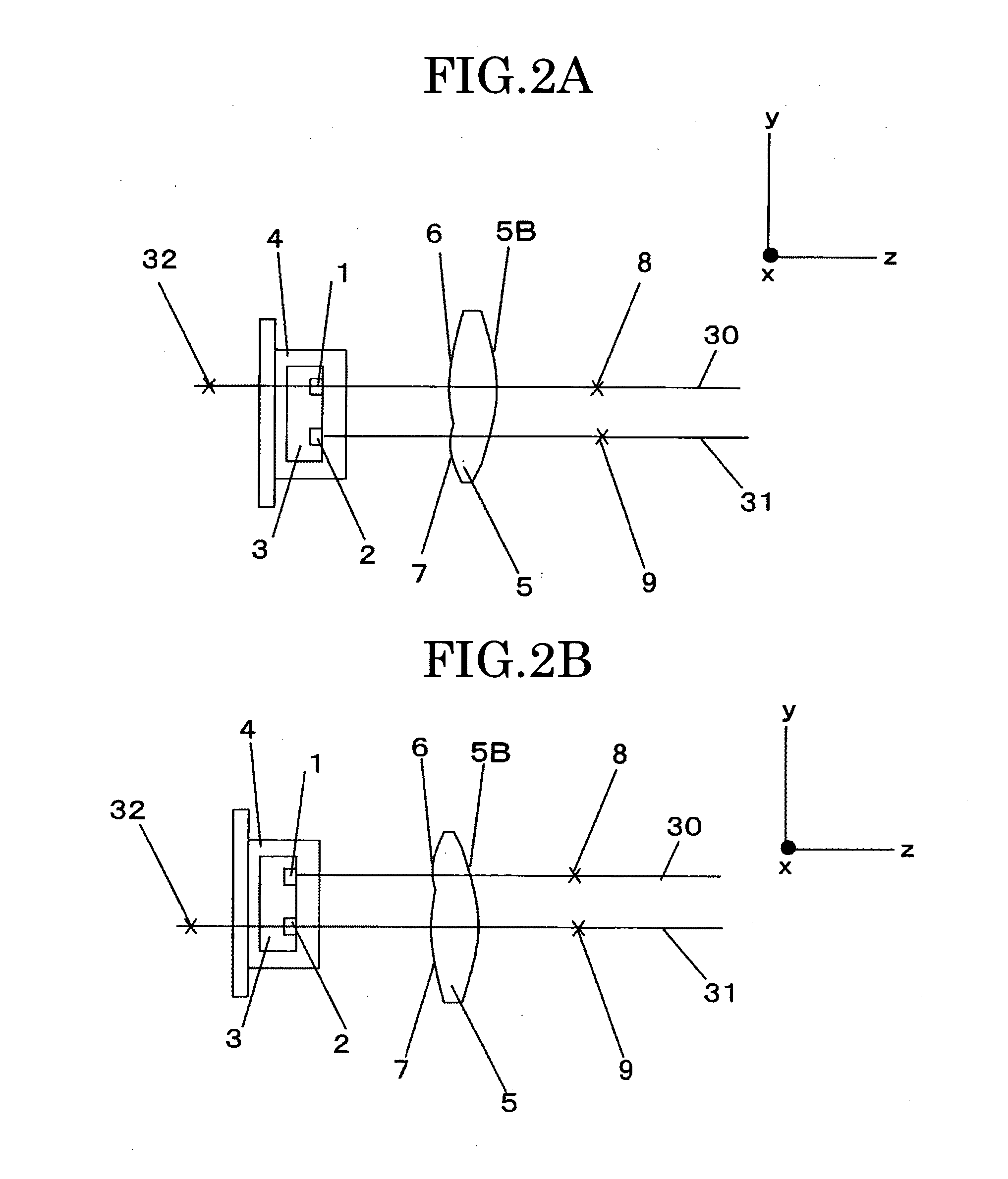
[0071]The light emitted from the light source which has the optical axis passing through positions of the curvature center 32 of the second surface 5B of the CL 5, which is opposite to the first surface 5A, and the curvature center 8 of the first region 6 of the first surface 5A of the CL 5 is reflected on the front surface 20 of the wedge prism 13.

[0072]The light flux reflected on the rear surface 21 of the wedge prism 13 has an astigmatism and the light flux reflected on the front surface 20 of the wedge prism 13 has no aberration in a case where the reflection surface 20 is an ideal planar surface. According to this configuration where the light passing through the opposite surfaces of the CL 5 without being relatively shifted is reflected on the front surface 20 of the wedge prism 13, good optical properties can be achieved.

[0073]On the other hand, the second surface 5B of the CL 5, which is opposite to the f...

third embodiment

[0075]the present invention will be explained with reference to FIG. 6.

[0076]The illuminating device according to this embodiment further includes a third light source 14 in addition to the first and second light sources 1, 2 described in the first embodiment (see FIG. 1).

[0077]More specifically, the third light source 14 is disposed so as to emit third light having a third wavelength in a direction which differs from the emitted direction of the first light from the first light source 1 and the second light from the second light source 2. In this embodiment, the third light is emitted in a direction substantially perpendicular to the first and second light. As the third light source 14, a green light source configured to emit the third light having the wavelength in a green color wavelength range of 500 nm to 550 nm may be used. A semiconductor laser is preferably used as the green light source. However, actually there exists no green semiconductor laser, which can be steadily used...


PUM


Abstract

A coupling lens for coupling first light having a first wavelength from a first light source with a second light having a second wavelength from a second light source disposed adjacent to the first light source in substantially the same direction includes a first surface disposed to face the first and second light sources, the first surface including a first region transmitting the first light and having a first region curvature and a second region transmitting the second light and having a second region curvature, and a second surface opposite to the first surface and having a second-surface curvature. A position of a center of the first region curvature differs from a position of a center of the second region curvature. A center of the second surface curvature and the center of the first region curvature are disposed on an optical axis of the first or second light source.

Description

[0001]This application is based on and claims priority from Japanese Patent Application No. 2008-321135, filed on Dec. 17, 2008, the disclosure of which is incorporated herein by reference in its entirety.TECHNICAL FIELD[0002]The present invention relates to an illuminating device configured to combine light modulated and emitted from a plurality of light sources and to emit the combined light in one direction. The present invention also relates to a coupling lens used in the illuminating device, a projection type image display apparatus such as a laser scanning type projector, and the like, having the illuminating device, and an electronic device such as a mobile phone and the like, where the projection type image display apparatus is disposed.BACKGROUND ART[0003]Recently, a projection type image display apparatus (hereinafter, referred to as a projector) using an LED, a laser, , or the like has been developed, and a small size portable projector is expected.[0004]In particular, a ...

Claims


Application Information

Patent Timeline
Patent Type & Authority Applications(United States)
IPC IPC(8): G02B27/12G03B21/14F21V13/04F21V5/04F21V5/02
CPCG02B27/0905G02B27/148G02B27/145G02B3/10G02B27/104F21V5/04G03B21/00
Inventor TAKAHASHI, YOSHITAKAAKIYAMA, HIROSHI
Owner RICOH KK
Why Eureka
Try Eureka