
Spring plate, lens actuator having same, and related camera module

a technology of spring plate and actuator, which is applied in the direction of printers, camera focusing arrangement, ring springs, etc., can solve the problems of bulky optical system and relatively large volume of step motor

Inactive Publication Date: 2011-10-13
HON HAI PRECISION IND CO LTD
View PDF4 Cites 28 Cited by
  • Summary
  • Abstract
  • Description
  • Claims
  • Application Information

AI Technical Summary

Benefits of technology

The present patent relates to a lens actuator for optical systems, particularly for camera modules. The technical effect of the patent is to provide a more compact and less mechanically movement lens actuator, a spring plate, and a camera module with the spring plate. This allows for a more compact and less bulky optical system. The spring plate is located between the lens and the image sensor, and includes a plurality of locating pins for fastening to the lens or the movable barrel. The spring plate is connected to the fixed unit or the movable barrel with adhesive. The technical effect of the patent is to provide a more efficient and compact lens actuator for camera modules.

Problems solved by technology

However, the step motor is relatively large in volume.
Use of the step motor requires a significant amount of space for movement of the lenses, which makes the optical system bulky.

Method used


Image

  • Spring plate, lens actuator having same, and related camera module
  • Spring plate, lens actuator having same, and related camera module
  • Spring plate, lens actuator having same, and related camera module

Examples


first embodiment

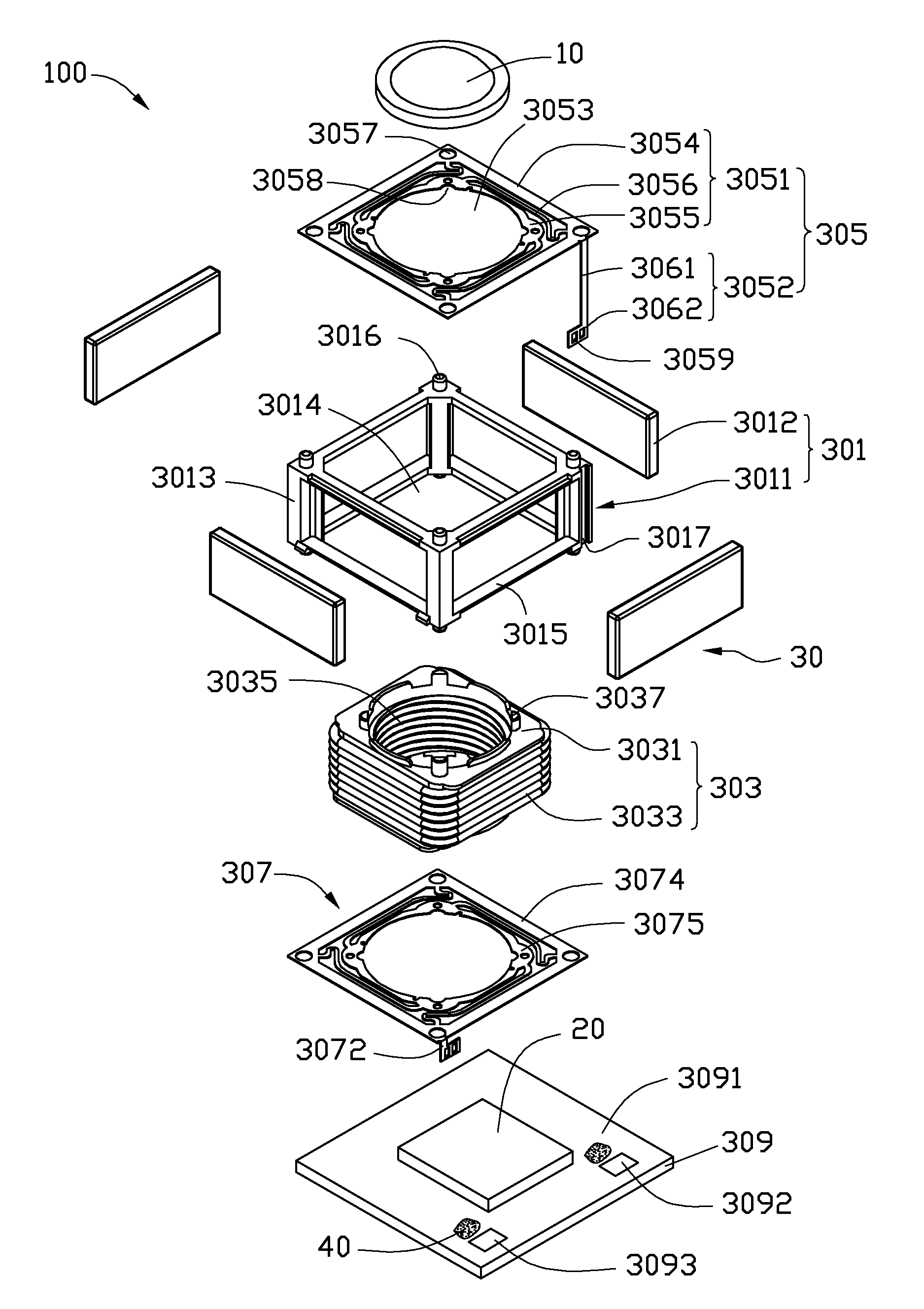
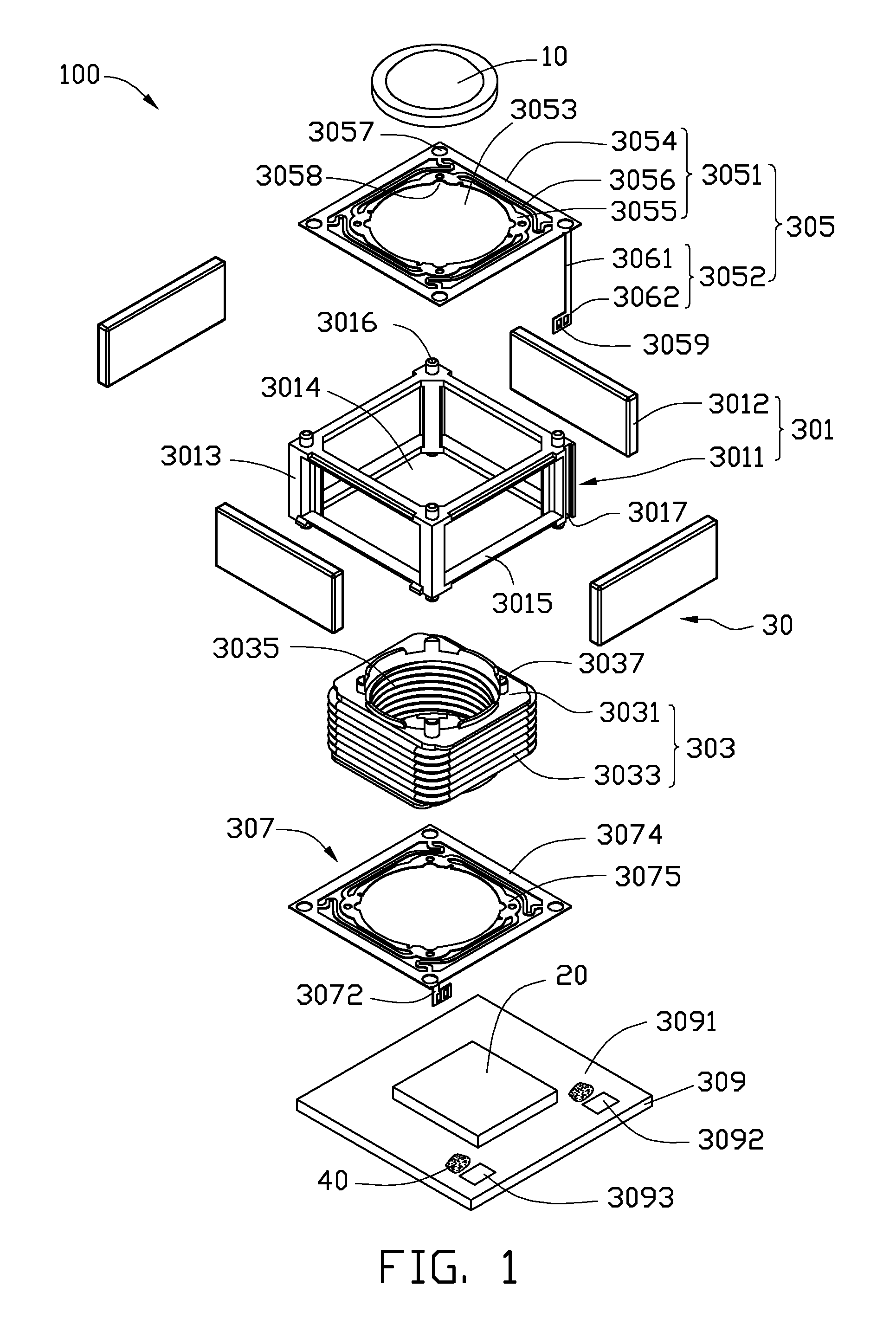
[0010]Referring to FIG. 1, a camera module 100 is shown. The camera module 100 includes a lens barrel (not shown), a lens 10 received in the lens barrel, an image sensor 20 for receiving light from the lens 10 and forming an image, and a voice coil motor 30. In other embodiments, there may be two, there or more lenses in the lens barrel.

[0011]The voice coil motor 30 includes a fixed unit 301, a movable unit 303, two spring plates 305, 307 respectively located on the two ends of the movable unit 303, and a supporting base 309.

[0012]The fixed unit 301 includes a cubic bracket 3011, and a plurality of magnets 3012. The cubic bracket 3011 includes a frame body 3013. A first accommodation chamber 3014 is defined in the frame body 3013. Four magnet mounting holes 3015 are respectively defined in four sides of the frame body 3013. The magnet mounting holes 3015 are in communication with the first accommodation chamber 3014, and are configured for receiving the magnets 3012. Four first loc...

second embodiment

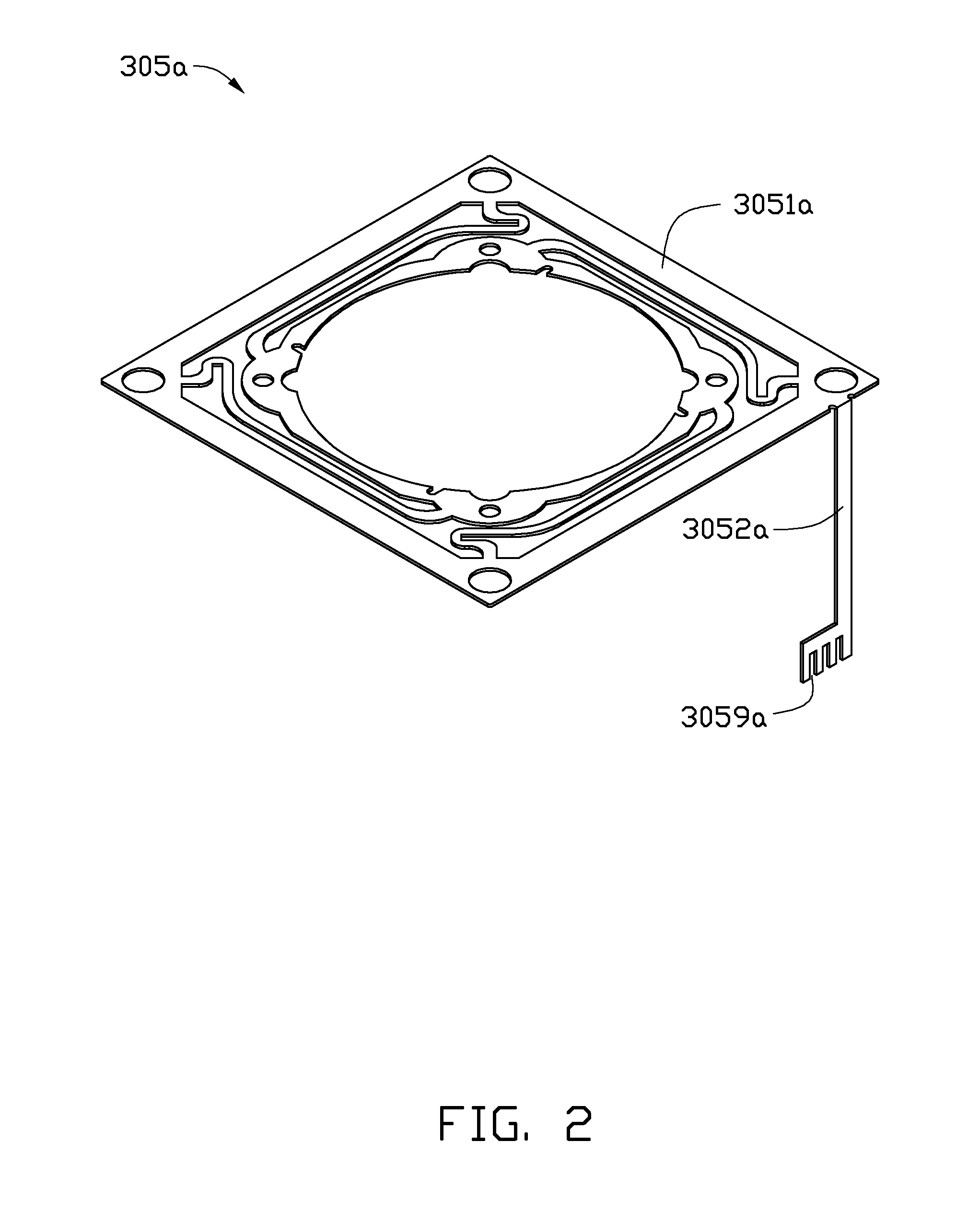
[0025]Referring to FIG. 2, a spring plate 305a, in accordance with a second embodiment, is shown. The spring plate 305a includes a plate body 3051a, and a terminal 3052b. A plurality of passable structures 3059b are defined in the end portion distal from the plate body 3051a of the terminal 3052b, and are recesses. The passable structures 3059 are exposed at a common edge of the terminal 3052b. In the present embodiment, the passable structures 3059b are exposed at a straight edge of the terminal 3052b, and cooperatively define a square wave pattern. In alternative embodiments, the passable structures 3059b may cooperatively define a saw tooth wave pattern.

third embodiment

[0026]Referring to FIG. 3, a spring plate 305b, in accordance with a third embodiment, is shown. The spring plate 305b includes a plate body 3051b and a terminal 3052b. A passable structure 3059b is defined in the end portion distal from the plate body 3051b of the terminal 3052b. In the present embodiment, the passable structure 3059b is a V-shaped recess. In other embodiments, the passable structure 3059 may be a U-shaped recess, a trapezoidal recess, etc.


PUM


Abstract

A spring plate includes a plate body having a through hole defined at the center thereof, and a terminal perpendicularly extending from the plate body. The plate body includes an outer closed-loop frame, an inner closed-loop frame, and spring parts interconnected between the outer closed-loop frame and the inner closed-loop frame. The terminal has an end portion distal from the plate body with at least one of a through hole and a recess therein.

Description

BACKGROUND[0001]1. Technical Field[0002]The present disclosure relates to lens actuators, and particularly, to a voice coil motor type lens actuator, a spring plate in the lens actuator, and a camera module with the spring plate.[0003]2. Description of Related Art[0004]Variable focal length lenses are widely used in optical systems. Optical systems incorporating such lenses can, for example, provide focused images of objects at varying distances without adjusting the distance between the lens and the image plane. Variable focal length lenses can also be used in optical systems that provide varying magnification without change of lenses.[0005]Generally, the optical system usually includes an actuator, such as a step motor, to drive the lenses. However, the step motor is relatively large in volume. Use of the step motor requires a significant amount of space for movement of the lenses, which makes the optical system bulky.[0006]Therefore, it is desirable to provide a lens actuator ada...

Claims


Application Information

Patent Timeline
Patent Type & Authority Applications(United States)
IPC IPC(8): G02B7/04F16F1/20H02K41/035
CPCF16F1/027G02B7/08G03B3/10F16F1/20H02K41/0356
Inventor KU, PING-HANCHIU, CHI-WEI
Owner HON HAI PRECISION IND CO LTD
Learn More