Mounting Arrangement with Mounting Aid and Orthodontic Bracket

a technology for mounting brackets and brackets, which is applied in the field of mounting brackets with mounting aids and orthodontic brackets, mounting aids or jigs and associated orthodontic brackets, can solve the problems of significant errors in bracket position determination, uneconomical for an individual orthodontist to acquire such equipment, and high cost and complexity of computer techniques, so as to improve the fixation of caps, reduce the amount of material used, and increase the elastic effect of slots

Inactive Publication Date: 2011-10-13
HEISER WOLFGANG
View PDF14 Cites 25 Cited by
  • Summary
  • Abstract
  • Description
  • Claims
  • Application Information

AI Technical Summary

Benefits of technology

[0023]The first end can also comprise preferably at least one opening, so that it is possible to grasp the aid with a suitable tool such as a pliers and to bend the first end. This usually makes it possible to achieve better fixation of the caps. Widening the first end can also be advantageous.
[0024]Yet another advantage is ...

Problems solved by technology

In the case of the “hand” method, the measurements in the mouth of the patient are usually very imprecise, which can lead to significant errors in the determination of the bracket positions.
Conversely, the computer technique is expensive and very complicated.
In view of the relatively small number of orthodontic treatments which make use of lingual brackets, it is uneconomical for an individual orthodontist to acquire such equipment.
This is a time-consuming task, because the acrylic material must be removed completely from the brackets.
The disadvantage of both approaches is that, if a bracket works itself loose from a tooth at any time during the course of the ...

Method used


Image

  • Mounting Arrangement with Mounting Aid and Orthodontic Bracket
  • Mounting Arrangement with Mounting Aid and Orthodontic Bracket
  • Mounting Arrangement with Mounting Aid and Orthodontic Bracket

Examples


first embodiment

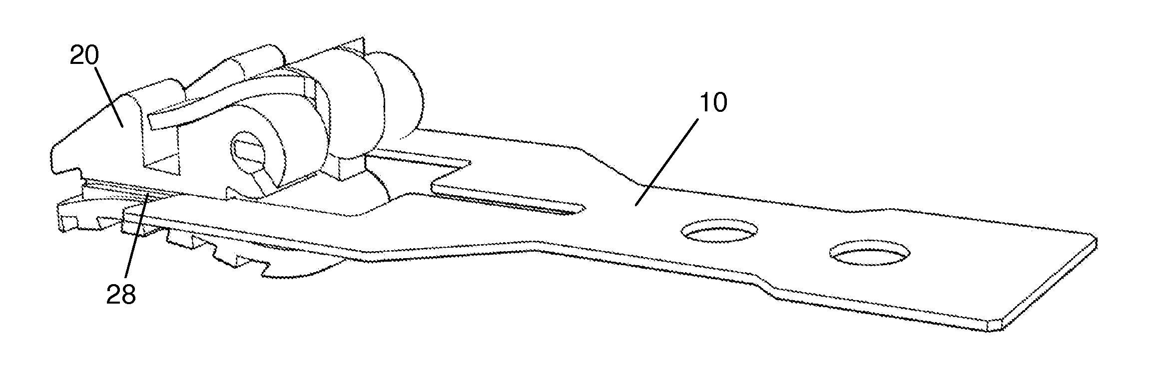
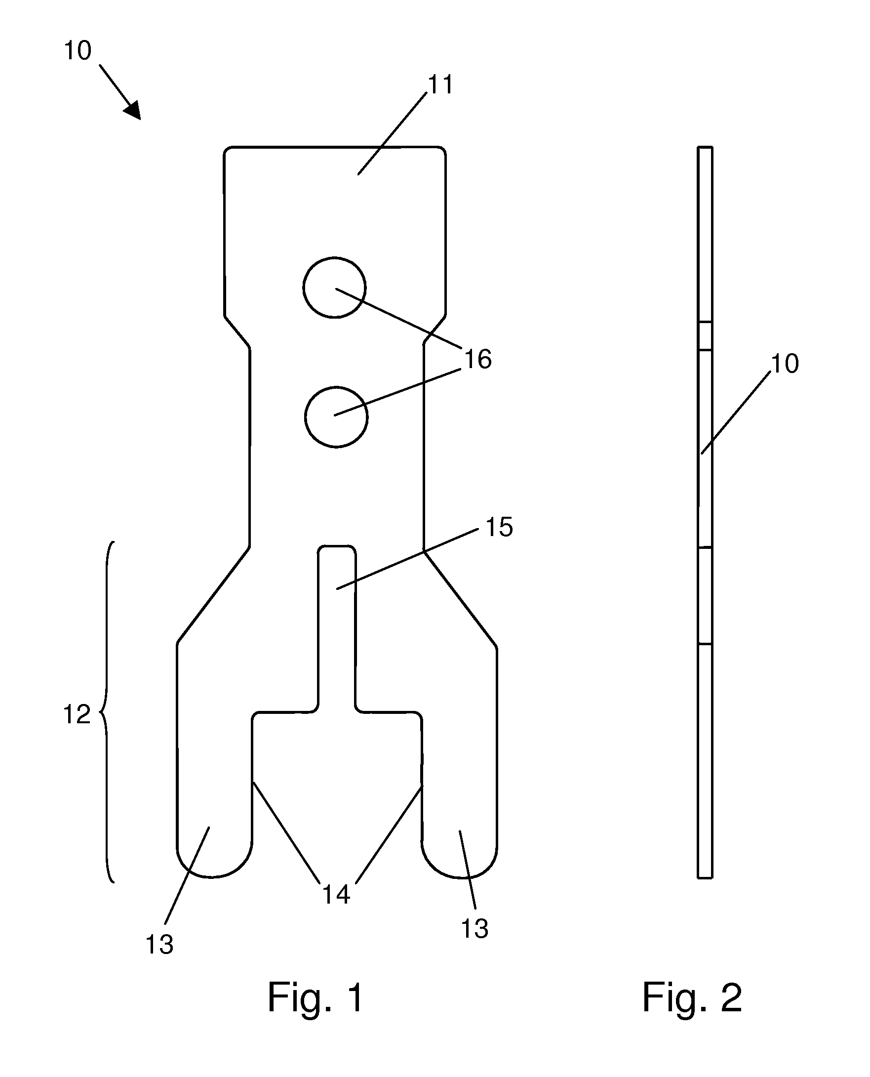
[0046]FIG. 1 shows a top view of an inventive aid 10 on a greatly enlarged scale. It should be noted in this relation that the components used for the inventive mounting arrangement, that is, the inventive mounting aid and the inventive bracket, are relatively small components, and accordingly all of the components are shown on an enlarged scale in all of the figures. The overall length of the mounting aid 10, for example, is approximately 10 mm; its greatest width is approximately 5 mm. The other details of the component are of corresponding size.

[0047]Mounting aid 10 is produced from a sheet metal strip with a thickness of about 0.2 mm. It comprises a first end 11, a central part, and a second end 12. In the embodiment shown in FIG. 1, mounting aid 10 is axially symmetric with respect to a center axis, which runs from first end 11 to second end 12. Second end 12 comprises two parallel side pieces 13 of essentially the same length, each of which comprises long inner sides 14, which...

second embodiment

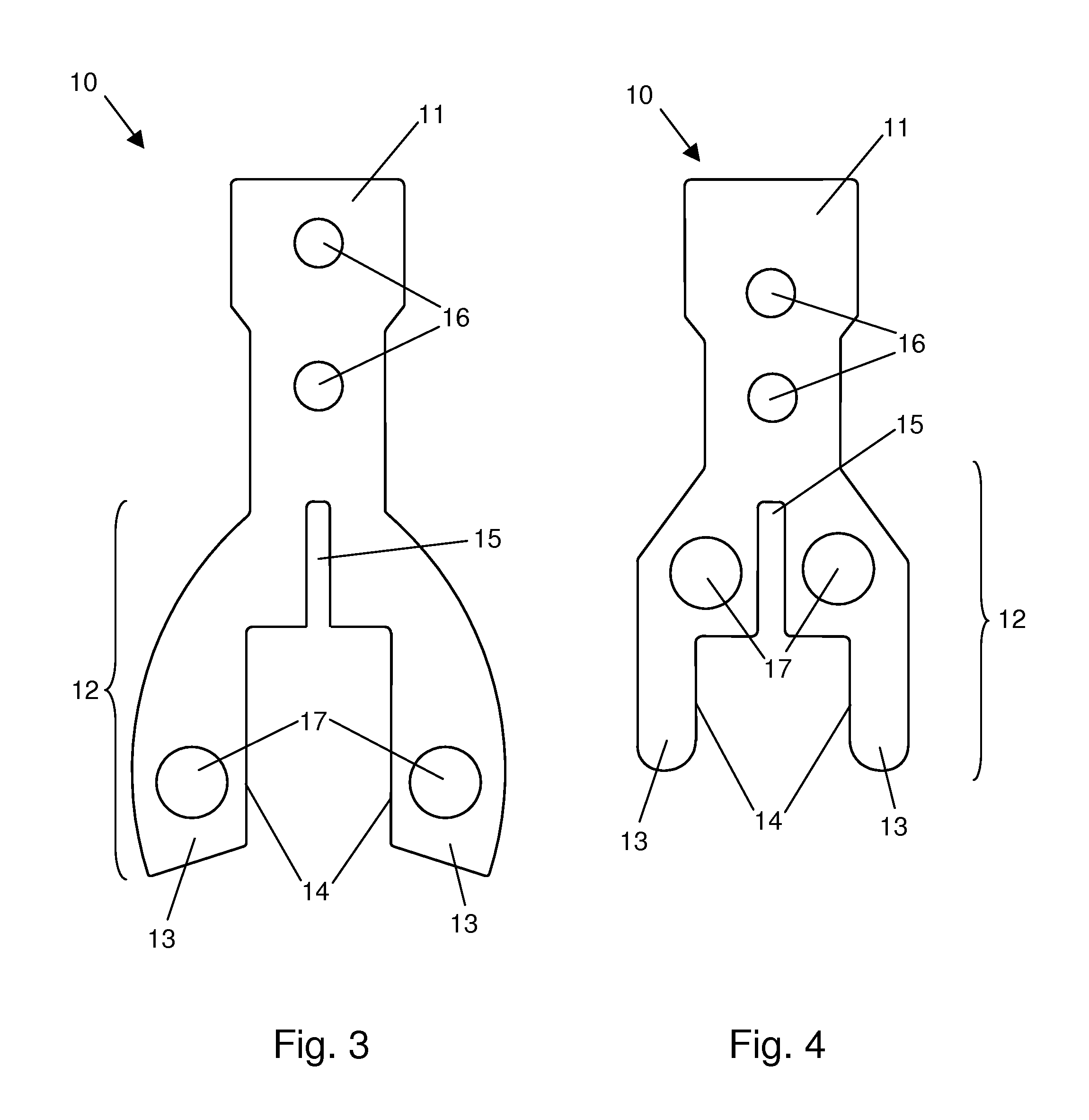
[0049]FIG. 3 shows a top view of an inventive mounting aid according to a The configuration of first end 11 is essentially identical to the configuration of mounting aid of FIG. 1, only the shape of side pieces 13 is different. It can be seen that side pieces 13 comprise a curved shape along their outer sides and that there is a round opening 17 at each end. A spreading pliers or a similar tool can engage in these openings 17 to move the side pieces apart and thus to support the process of pushing the aid onto, or of removing it from, a bracket. The shape of opening 17 does not have to be round; other suitable shapes such as elliptical, rectangular, polygonal, or the like can also be used.

[0050]FIG. 4 shows a top view of an inventive mounting aid according to another embodiment, wherein second end 12 comprises an opening 17 on each of the two sides of the slot 15, into which a spreading pliers as described above can positioned and engaged. In contrast to the exemplary embodiment sh...


PUM


Abstract

The invention concerns a mounting arrangement for mounting an orthodontic bracket on a tooth. The mounting arrangement comprises an orthodontic bracket and a mounting aid, wherein the mounting aid can be detachably connected to the orthodontic bracket with positive engagement by pushing it onto the bracket in such a way that long sides of the side pieces of the mounting aid engage in guide grooves of the bracket.

Description

CROSS REFERENCE TO RELATED APPLICATION[0001]This application claims priority based on European patent application EP 10 159 393.7, filed Apr. 8, 2010.FIELD OF THE INVENTION[0002]The present invention pertains to a mounting arrangement for the correction of malpositioned teeth with the help of orthodontic brackets, especially to a mounting aid or jig and an associated orthodontic bracket.BACKGROUND OF THE INVENTION[0003]One way of correcting malpositioned teeth is to use brackets, which are cemented in predefined positions to the teeth of the upper and lower jaws of the patient and then connected to each other by means of an elastic arch wire. The brackets on the individual teeth are installed in positions which are selected so that, at the end of the orthodontic treatment, the arch wire passing through the brackets is essentially free of waves or undulations. At the beginning of the treatment, the arch wire therefore comprises a highly complex course. Depending on the degree to whic...

Claims


Application Information

Patent Timeline
IPC IPC(8): A61C7/02A61C7/12
CPCA61C7/146
Inventor HEISER, WOLFGANG
Owner HEISER WOLFGANG
Why Eureka
Try Eureka