Delivery System Ejection Component and Method

a delivery system and stent technology, applied in the field of medical devices and procedures, can solve the problems of difficult repositioning room for error in placement, and difficult retraction of the stent-graft after initial deployment, except for a minimal pull down retraction

Active Publication Date: 2011-10-13
MEDTRONIC VASCULAR INC
View PDF2 Cites 27 Cited by
  • Summary
  • Abstract
  • Description
  • Claims
  • Application Information

AI Technical Summary

Benefits of technology

[0029]In this example, the ejection collar is a hollow cylinder having a longitudinal axis coincident with the longitudinal axis of the spindle tube. The ejection collar components (elements) comprise a material having elastic deformation properties. When a stent is constrained on spindle pins of the spindle by the retaining sleeve, the ejection collar is elastically deformed by the stent. When the stent is no longer constrained by the retaining sleeve, the energy of the constrained ejection collar is released to cause the collar elements to spring radially outward to help move crowns of the stent off the spindle pins.

Problems solved by technology

Such a configuration leaves little room for error in placement since re-positioning the stent-graft after initial deployment, except for a minimal pull down retraction, is difficult, if possible at all.

Method used


Image

  • Delivery System Ejection Component and Method
  • Delivery System Ejection Component and Method
  • Delivery System Ejection Component and Method

Examples


Embodiment Construction

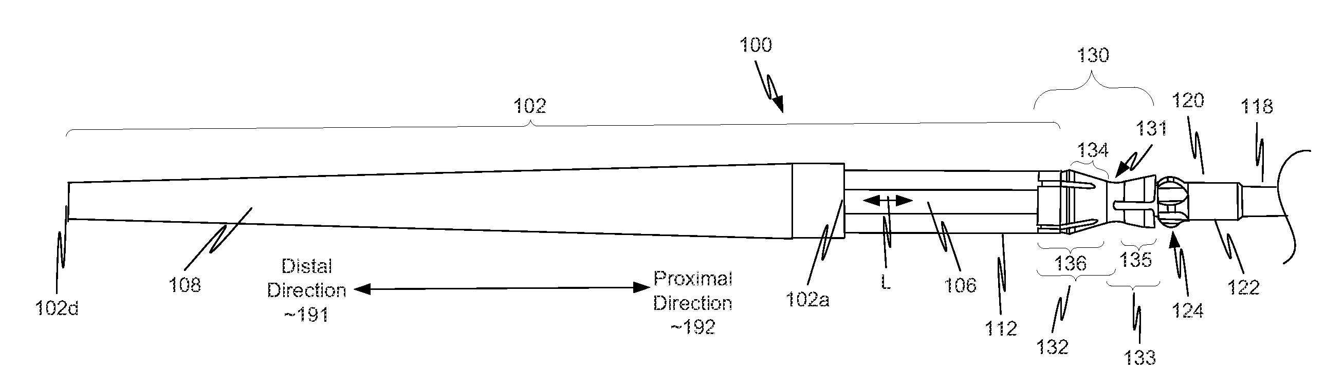
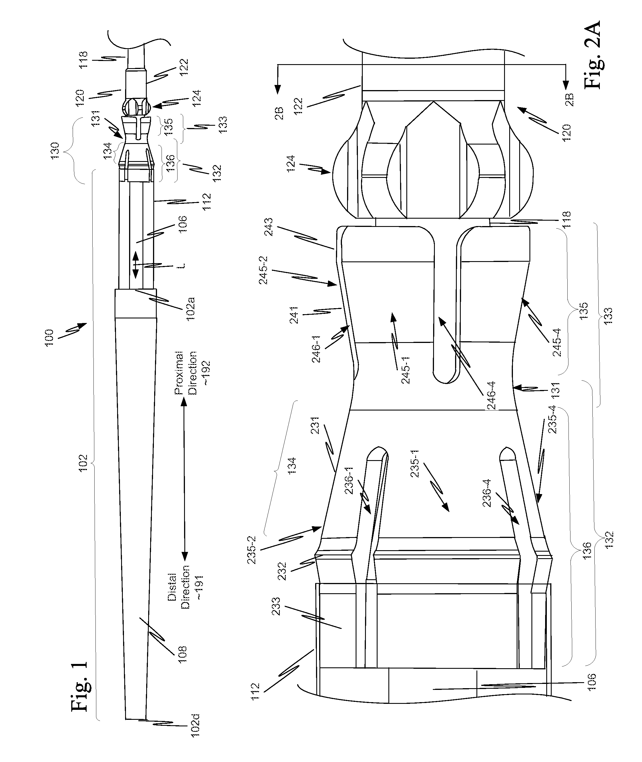
[0040]As illustrated in FIG. 1, in a first example, a component 130 is located on a distal portion of a stent delivery system 100. Component 130 includes both a retaining-sleeve landing component 132 and a stent ejection component 133. Retaining-sleeve landing component 132 includes a body 131 and a landing collar 136. Stent ejection component 133 includes body 131 and an ejection collar 135. Thus, in this example, retaining-sleeve landing component 132 and stent ejection component 133 share body 131.

[0041]While in the example of FIG. 1, component 130 includes both stent ejection component 133 and retaining-sleeve landing component 132, this is illustrative only and is not intended to be limiting. In view of this disclosure, a component can include only one of stent ejection component 133 and retaining-sleeve landing component 132. These alternatives follow directly from the example discussed more completely below with respect to FIGS. 1, 2A, 2B and 3. Thus, drawings of a delivery s...


PUM


Abstract

A stent or stent-graft delivery system includes a stent ejection component. The stent ejection component includes a body and an ejection collar. The ejection collar extends from the body in the proximal direction. The ejection collar assists in automatically ejecting a proximal end of a stent when the tapered tip is moved in the distal direction to deploy the stent. A stent or stent-graft delivery system may also include a retain-sleeve landing component. The retaining-sleeve landing component includes a body and a landing collar. The landing collar extends from the body in a distal direction. The landing collar automatically captures a tapered tip of the delivery system when the tapered tip is moved in a distal direction to deploy a stent contained in the delivery system. Upon capture of the tapered tip, the stent ejection component with the tapered tip attached has an atraumatic profile.

Description

BACKGROUND[0001]1. Field of Invention[0002]This invention relates generally to medical devices and procedures, and more particularly to a method and system of deploying a stent in a vascular system.[0003]2. Related Art[0004]Prostheses for implantation in blood vessels or other similar organs of the living body are, in general, well known in the medical art. For example, prosthetic vascular grafts formed of biocompatible materials (e.g., Dacron or expanded polytetrafluoroethylene (ePTFE) tubing) have been employed to replace or bypass damaged or occluded natural blood vessels.[0005]A graft tube material supported by a framework is known as a stent-graft or endoluminal graft. In general, the use of stents and stent-grafts for treatment or isolation of vascular aneurysms and vessel walls which have been thinned or thickened by disease (endoluminal repair or exclusion) is well known.[0006]Many stents and stent-grafts are “self-expanding”, i.e., inserted into the vascular system in a com...

Claims


Application Information

Patent Timeline
Patent Type & Authority Applications(United States)
IPC IPC(8): A61F2/84
CPCA61F2/07A61F2/95A61F2250/0039A61F2002/9665A61F2/966A61F2/9661
Inventor SCHMITT, JOSHUA J.ARGENTINE, JEFFERY
Owner MEDTRONIC VASCULAR INC
Why Eureka
Try Eureka