Self-centering ceiling panel

a ceiling panel and self-centering technology, applied in the field of ceiling panels, can solve the problems of inflexible panels, frequent replacement of acoustic panels, and difficult inserting,

Active Publication Date: 2011-10-20
CERTAINTEED CEILING
View PDF4 Cites 23 Cited by
  • Summary
  • Abstract
  • Description
  • Claims
  • Application Information

AI Technical Summary

Benefits of technology

[0009]The ceiling panel itself is made of steel or aluminum but includes clips made of a semi-rigid but resilient material such as spring steel so the panel is positionable within an opening in the gridwork so as to be self-centered within the opening and also in a manner so that it does not easily change positions within its opening and is not subjected to compressive shear forces which might distort or bow the panel over time.

Problems solved by technology

Most drop ceiling panels are made of an acoustic tile which have certain desirable characteristics as far as aesthetics and sound absorption is concerned, but such panels are inflexible and it is very difficult to insert a panel into an opening in the gridwork so it can rest on the stringers defining the grid system in a uniform manner.
Many times such acoustical panels will break during installation or become discolored or water stained thereby necessitating replacement of the ceiling panel and, accordingly, there is considerable waste and frequent replacement of acoustical panels in a drop ceiling.
Metal panels, however, typically have spring clips along the side edges thereof which are biased outwardly into engagement with the stringers in the supporting gridwork, and while the springs are helpful in holding the panel in the desired position within the gridwork, they typically place the panel under shear compression so that over time the panel may undesirably bow disrupting the aesthetic continuity of the drop ceiling.

Method used


Image

  • Self-centering ceiling panel
  • Self-centering ceiling panel
  • Self-centering ceiling panel

Examples


Embodiment Construction

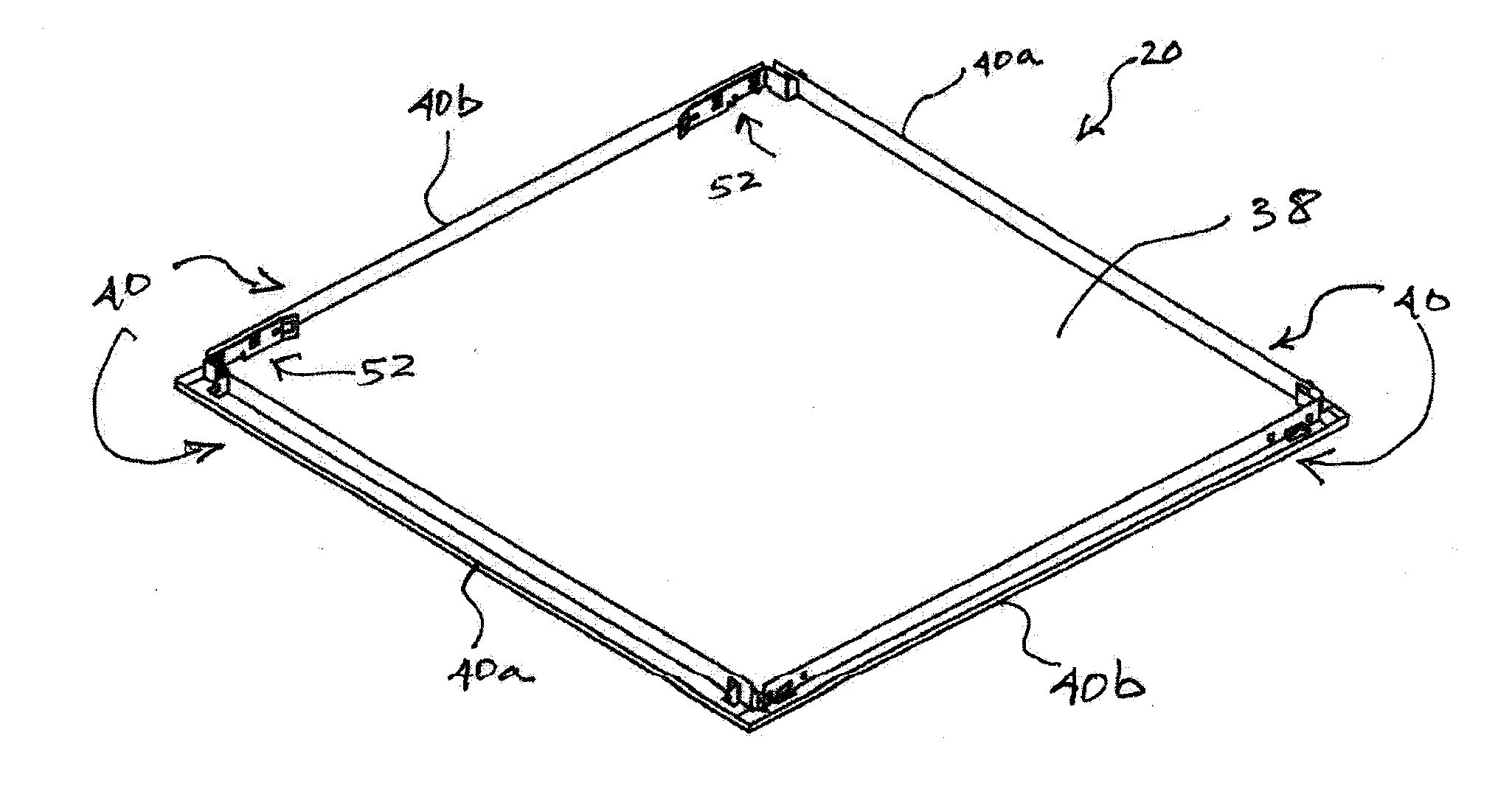
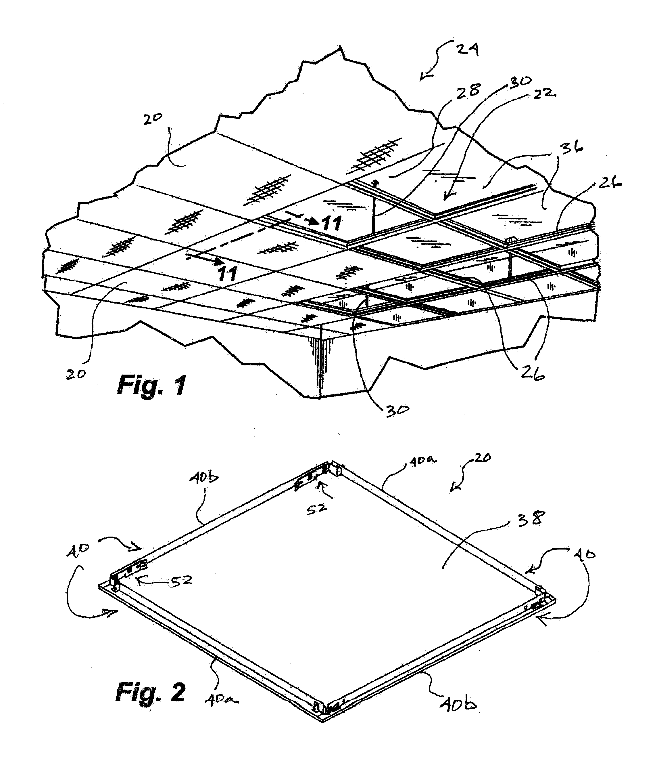
[0028]The ceiling panel 20 of the present invention is designed to be used in a conventional suspended gridwork 22 of a drop ceiling system 24 of the type seen best in FIG. 1. It can there be appreciated that a plurality of mutually perpendicular stringers 26 are suspended from an overhead ceiling 28 with suspension rods 30 so that a gridwork of such stringers is defined in a horizontal plane. Each stringer is of inverted T-shaped cross-section as can be seen best in FIGS. 11-16 having a vertical web 32 connected to the suspension rods and flanges or shoulders 34 projecting in opposite directions from the vertical web along its lowermost edge. The shoulders are adapted to support a ceiling panel 20 in a manner such that when looking upwardly at the drop ceiling, an observer sees the panels in closely spaced and aligned relationship with the stringers substantially blocked from vision. Quadrangular openings 36 defined by the stringers can be square or rectangular depending upon the d...


PUM


Abstract

A panel for a drop ceiling is made of a semi-rigid but resilient material such as spring steel and includes corner clips adapted to cooperate with the inverted T-shaped stringers of a drop ceiling support system so that the panel is self-centering between opposing stringers and is spring biased into a clamped relationship with horizontal flanges of the inverted T-shape stringers to prevent the panel from moving up and down. The corner clips are also designed to transfer any horizontal compressive shear force in the mounting system to vertical edges of the panel so as not to undesirably bow the flat base of the panel.

Description

CROSS REFERENCE TO RELATED APPLICATION[0001]This application claims priority to U.S. provisional application No. 61 / 325,066, entitled “Self-Centering Ceiling Panel” filed on Apr. 16, 2010, which is hereby incorporated herein by reference in its entirety.BACKGROUND OF THE INVENTION[0002]1. Field of the Invention[0003]The present invention relates generally to drop ceiling systems and more particularly to a ceiling panel that can be inserted into and supported by a gridwork suspended from a ceiling. The panel is made from a semi-rigid and resilient material having each side edge of the panel folded upwardly to define horizontal and vertical edges which receive removable clips in each corner of the panel that are in turn adapted to be releasably connected to the suspended gridwork of the ceiling system. The clips are designed so that each panel will be self-centered within an opening in the supporting gridwork and are snapped into the opening in a manner so as not to place compressive ...

Claims


Application Information

Patent Timeline
Patent Type & Authority Applications(United States)
IPC IPC(8): E04B9/18
CPCE04B9/245E04B9/0478
Inventor BAILEY, DAVIDKUPERUS, KOMAYER, RICHARD
Owner CERTAINTEED CEILING
Why Eureka
Try Eureka