Slitting Machine for Longitudinally Cutting Material Where The Cut is Critical

Inactive Publication Date: 2011-10-20
DIENES CORP
View PDF3 Cites 5 Cited by
  • Summary
  • Abstract
  • Description
  • Claims
  • Application Information

AI Technical Summary

Benefits of technology

[0008]The basic concept of the present invention is that a non-cutting tool is disposed upstream of the cutting arrangement, as viewed in the cutting or slitting direction, for producing a cutting channel in a surface of a sheet of material, wherein the cutting arrangement is adapted to enter the cutting channel and to execute the cut or slit along the cutting channel. In this regard, a cutting track or channel is first introduced into the surface of the material that is to be cut by means of the non-cutting tool. If the cut is then executed along the cutting channel by means of the cutting arrangement, which enters or extends into this cutting channel, there results in a surprising and unexpected manner a clean and smooth slit edge.
[0009]Pu

Problems solved by technology

If such a slitting machine is to be used for cutting a material, for example a fibrous and in particular coarsely fibrous material, as a material for which the cut is critical, there is the drawback that the slitting line or line of cut pro

Method used


Image

  • Slitting Machine for Longitudinally Cutting Material Where The Cut is Critical
  • Slitting Machine for Longitudinally Cutting Material Where The Cut is Critical

Examples


Embodiment Construction

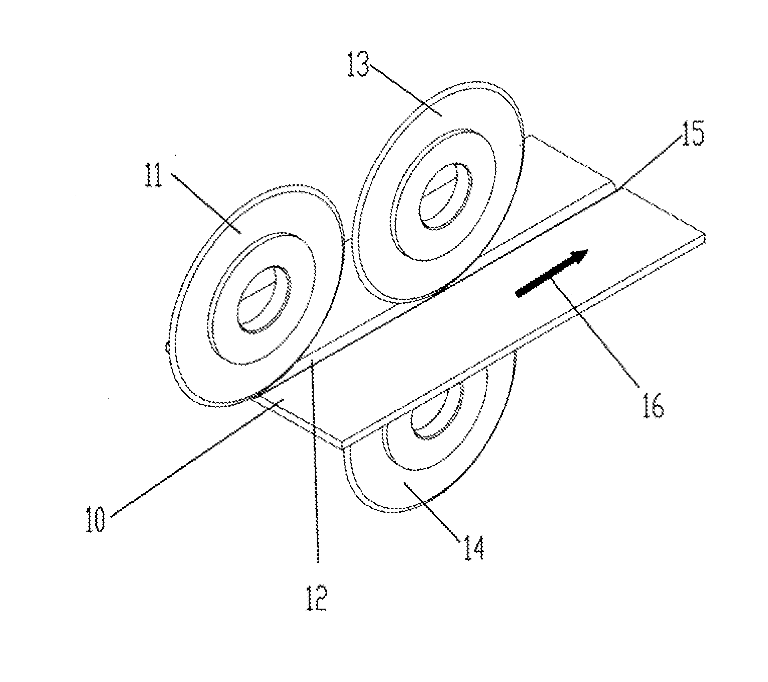
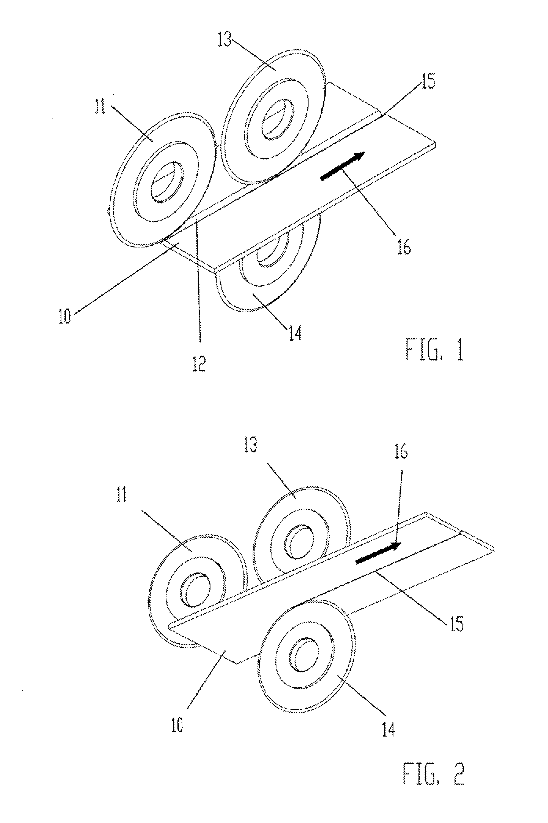
[0016]The figures show a sheet of material 10 that is moved in the direction of the arrow 16 and that is to be cut or separated along a slitting line or line of cut 15 by means of a cutting or slitting arrangement that is composed of an upper blade 13 and an associated lower blade 14. Disposed upstream of the arrangement composed of the upper blade 13 and the lower blade 14 is a non-cutting tool or instrument 11, for example in the form of a crushing blade, which is known per se; the tool 11 serves to press a cutting track or channel 12 into the surface, in the illustrated embodiment the upper surface, of the sheet of material 10. The downstream upper blade 13 enters into the cutting channel 12 produced by the tool 11, and in cooperation with the lower blade 14 executes the cut or slit in this cutting channel 12 along the slitting line 15, wherein the shearing cut principle is preferably utilized. Within the framework of such an arrangement, even with a fibrous, in particular coarse...


PUM

PropertyMeasurementUnit
Depthaaaaaaaaaa

Abstract

A slitting machine for slitting or longitudinally cutting material, especially fibrous material, where the cut is critical. A cutting arrangement produces a slit or cut that divides a sheet of material, the cutting arrangement comprising an upper blade and a lower blade. A non-cutting tool for producing a cutting channel in a surface of the sheet of material is disposed upstream of the cutting arrangement as viewed in a direction of slitting. The cutting arrangement is adapted to enter the cutting channel and to execute a cut or slit along the cutting channel.

Description

[0001]The instant application should be granted the priority date of Apr. 14, 2010 the filing date of the corresponding German patent application 20 2010 005 010.3.BACKGROUND OF THE INVENTION[0002]The present invention relates to a slitting machine for slitting or longitudinally cutting material, especially fibrous material, where the cut is critical, and includes a cutting arrangement, comprised of an upper blade and a lower blade, for producing a slit or cut that divides the material.[0003]A slitting machine having the aforementioned features is known from DE 20 2006 017 387 U1. If such a slitting machine is to be used for cutting a material, for example a fibrous and in particular coarsely fibrous material, as a material for which the cut is critical, there is the drawback that the slitting line or line of cut produced by the cutting arrangement, which is provided with an upper blade and an associated lower blade, becomes frayed in conformity with the fiber structure of the mater...

Claims


Application Information

Patent Timeline
IPC IPC(8): B26D7/08
CPCB26D1/24B26D3/085B26D9/00B26D7/10B26D7/086Y10T83/343
Inventor SUPE-DIENES, RUDOLF
Owner DIENES CORP
Why Eureka
Try Eureka