Multi-Angle Colorimeter

Active Publication Date: 2014-02-20
KONICA MINOLTA INC
View PDF2 Cites 5 Cited by
  • Summary
  • Abstract
  • Description
  • Claims
  • Application Information

AI Technical Summary

Benefits of technology

[0013]According to the structure, the main signal is corrected based on the information about the light component obtained from the plurality of auxiliary optical windows disposed on the plane which includes the predetermine

Problems solved by technology

If a measuring target is a sample having a curvature, for example, a bumper of a car or the like, however, there is a high possibility that a

Method used


Image

  • Multi-Angle Colorimeter
  • Multi-Angle Colorimeter
  • Multi-Angle Colorimeter

Examples


first embodiment

2. First Embodiment

[0065]The functional configurations of a light detecting portion 40 and a calculating portion 72 in a multi-angle colorimeter 100 according to a first embodiment will be described, and furthermore, a method of correcting a posture error according to the present invention will be described together.

[0066]

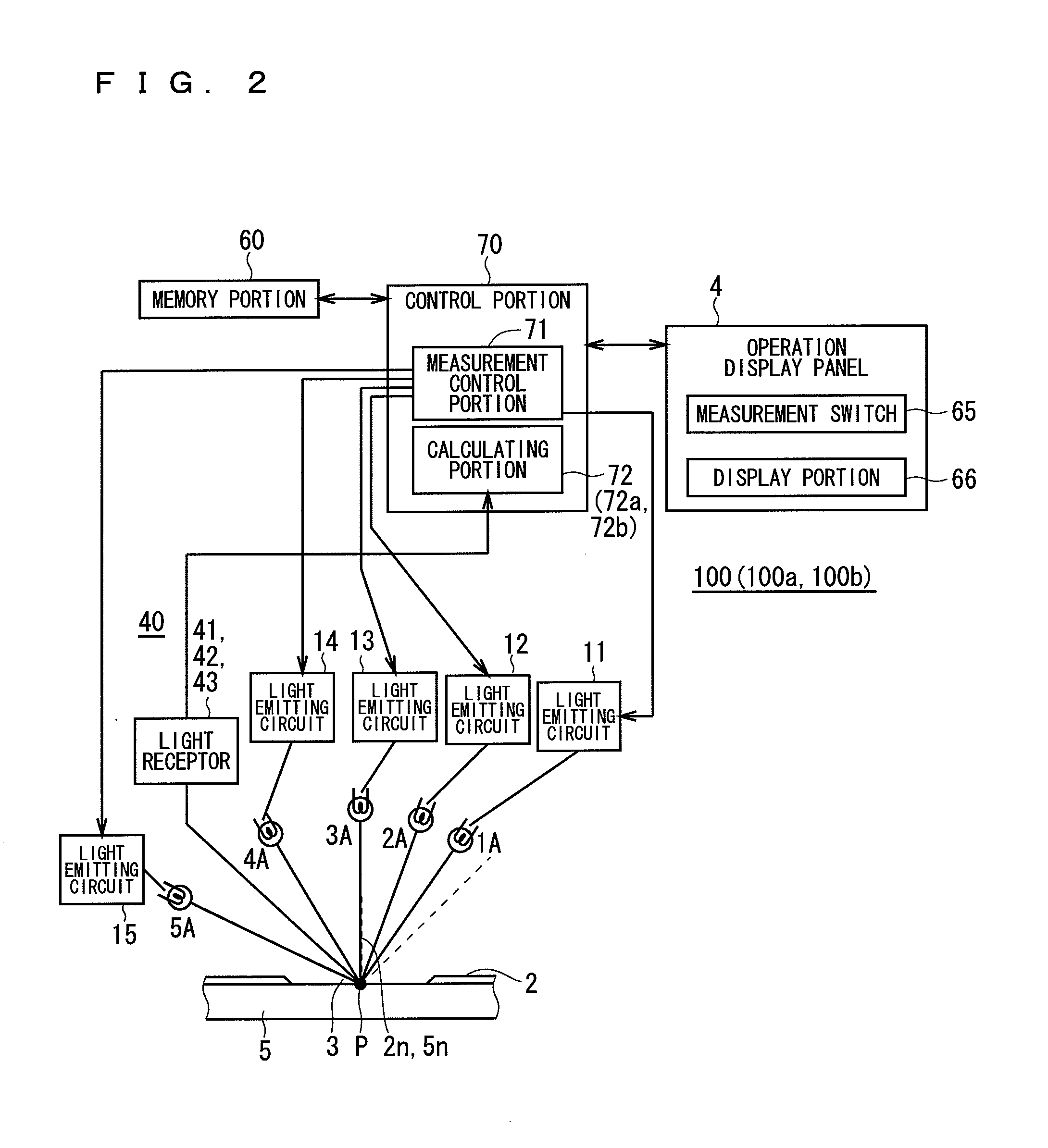
[0067]Above all, the functional configuration of the light detecting portion 40 in the multi-angle colorimeter 100 will be described (see FIG. 2).

[0068]FIG. 5 is a view showing an example of a structure of the light detecting portion 40 in a secondary geometry plane of the multi-angle colorimeter 100 according to the present embodiment, and FIG. 6 is a diagram showing the functional configurations of the light detecting portion 40 and the calculating portion 72.

[0069]As an example of the present invention,

[0070](I) Arrangement of a plurality of auxiliary light receiving windows on a single side with respect to a main geometry plane,

[0071](II) Arrangement of a plura...

second embodiment

3. Second Embodiment

[0108]

[0109]Although a basic functional configuration of a multi-angle colorimeter 100a according to a second embodiment of the present invention is almost the same as that in the first embodiment as shown in FIG. 2, a function of a calculating portion 72a is different from that in the first embodiment. Since the residual configurations are the same as those of the device according to the first embodiment, only different respects will be described.

[0110]As shown in FIG. 6, an approximation function estimating portion 73 is provided as the function of the calculating portion 72a in the same manner as in the first embodiment, and functions of a correction factor calculating portion 74a and a correcting portion 75a are different.

[0111]The correction factor calculating portion 74a calculates a ratio R of measured values of first and second auxiliary signals SG1 and SG2, in the case where a posture error occurs, based on an approximation function F obtained by the app...

third embodiment

4. Third Embodiment

[0127]In the case in which a posture error exceeding an acceptable limit is made, there is also a possibility that the measurement precision might be poorer due to forcible execution of the correction. Therefore, a multi-angle colorimeter 100b which will be described below has a function for displaying an error and promoting a user to carry out measurement again when it is estimated that the posture error exceeds a certain value.

[0128]

[0129]Although a basic functional configuration of the multi-angle colorimeter 100b according to a third embodiment of the present invention is almost the same as that in the first embodiment as shown in FIG. 2, a function of a calculating portion 72b is different from that in the first embodiment. Since the residual configurations are the same as those of the device according to the first embodiment, only different respects will be described.

[0130]As shown in FIG. 6, an approximation function estimating portion 73 is provided as the...


PUM


Abstract

In a multi-angle colorimeter, a light detecting portion 40 includes a main light receiving window disposed in a predetermined position on a main geometry plane, and first and second auxiliary light receiving windows disposed on a secondary geometry plane, and a main photoelectric conversion element for converting a main component light received by the main light receiving window in a light reflected from a measurement point into an electrical main signal and first and second auxiliary photoelectric conversion elements for converting first and second auxiliary component lights received by the first and second auxiliary light receiving windows in the reflected light respectively into first and second electrical auxiliary signals. A calculating portion corrects the electrical main signal based on the first and second electrical auxiliary signals to obtain color information about the measurement point.

Description

TECHNICAL FIELD[0001]The present invention relates to a multi-angle colorimeter and more particularly to a technique for improving an optical configuration for correcting a posture error of a colorimeter with respect to a measurement plane.BACKGROUND ART[0002]In some cases, a color of metallic painting, pearl color painting and the like to be used in painting for a car and the like is seen to be different depending on a direction of an observer under the influence of a brilliant material in an inner part. For this reason, a multi-angle colorimeter for carrying out illumination or light reception at a plurality of angles is used for evaluation of the painting (evaluation of a paint color).[0003]In other words, the metallic painting and the pearl color painting which is to be used in painting for a car and the like is constituted by containing, in a painted film, a flaky aluminum piece and mica piece which is referred to as a brilliant material and produces a so-called metallic effect...

Claims


Application Information

Patent Timeline
IPC IPC(8): G01J3/50
CPCG01J3/50G01J3/502G01J3/504G01N21/251G01N21/255G01N2021/4711G01N2021/4735G01N2021/575G01N2201/0221
Inventor TERAOKA, YOSHITAKATSURUTANI, KATSUTOSHIYAMANOI, YUTA
Owner KONICA MINOLTA INC
Why Eureka
Try Eureka