Mass transfer column and a crown element for a mass transfer column

a mass transfer column and crown element technology, applied in the direction of machine supports, building scaffolds, domestic objects, etc., can solve the problems of inflexible collars according to the prior art, high manufacturing steps of screwing or riveting, and the mass transfer process is impacted, so as to achieve less costly

Active Publication Date: 2011-10-20
SULZER MANAGEMENT AG
View PDF5 Cites 1 Cited by
  • Summary
  • Abstract
  • Description
  • Claims
  • Application Information

AI Technical Summary

Benefits of technology

[0010]The problem of the invention is to provide a solution which is less costly than the above-mentioned prior art and by which a liquid by-pass along the column wall can be largely avoided.
[0016]At least one of the wall element, the roof element and the bottom element has, in a preferred embodiment, a thickness of from 0.05 to less than 0.2 mm. A sheet of a smaller thickness as compared to the prior art can follow the curvature of the column wall more accurately. Therefore, any leaks between the first bending line and the column wall are avoided to a large extent.
[0018]Surprisingly, it could be shown by the inventors, that by foreseeing longer and / or higher roof element segments, the curvature of the column wall was more accurately followed by the roof element segments when installed in the column.
[0020]An opening can be provided in at least one of the wall element, the roof element or the bottom element. Such an opening is used for directing any liquid, which trickles along the column wall back towards the packing. Such by-pass liquid can thus participate again in mass transfer when directed to the packing. Therefore the performance of the mass transfer column can be improved.
[0027]Thus, the height of the roof element and thus the height of each of the roof element segments is greater than the height of corresponding prior art solutions, which additionally improves the alignment of the roof element segments to the curved column wall. Thus according to a preferred embodiment the roof element edge has a curved shape. In other words, the roof element edge follows the curvature of the column wall due to the possibility of warpage mentioned previously, which is not possible if the height of the roof element segment is less than 15 mm and the thickness of the roof element segment is about 2 mm or more.

Problems solved by technology

However, it cannot be avoided in practice that a certain proportion of the liquid does spill over against the column wall and thereby impair the mass transfer process.
Since the packing consists of thin-walled material, the fastening of the collars, which may be done by welding, screwing or riveting is an expensive manufacturing step.
The loose collars according to the prior art are not flexible and consequently do not provide an adequate sealing.
This has the consequence that in operation a liquid by-pass occurs next to the column wall, which results in a decrease of the column performance.
Due to their geometrical arrangement, the loose collars may be flattened and destroyed in particular, when the packing has to be assembled into a column wall, which has a horizontal longitudinal axis.

Method used


Image

  • Mass transfer column and a crown element for a mass transfer column
  • Mass transfer column and a crown element for a mass transfer column
  • Mass transfer column and a crown element for a mass transfer column

Examples


Embodiment Construction

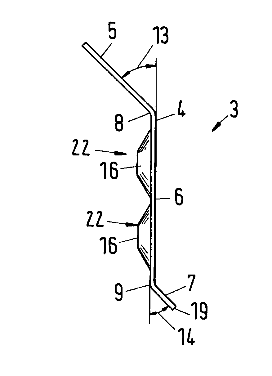
[0040]FIG. 1 is a detail of a cross-section of a crown element 3. The crown element 3 comprises an elongate sheet 4, of which a portion is shown also in FIG. 2. This elongate sheet 4 comprises a roof element 5, a wall element 6 and a bottom element 7. The wall element 6 is arranged between the roof element 5 and the bottom element 7. The roof element is arranged in an angle 13 with respect to the wall element 6. Also the bottom element 7 is arranged in an angle 14 to the wall element 6.

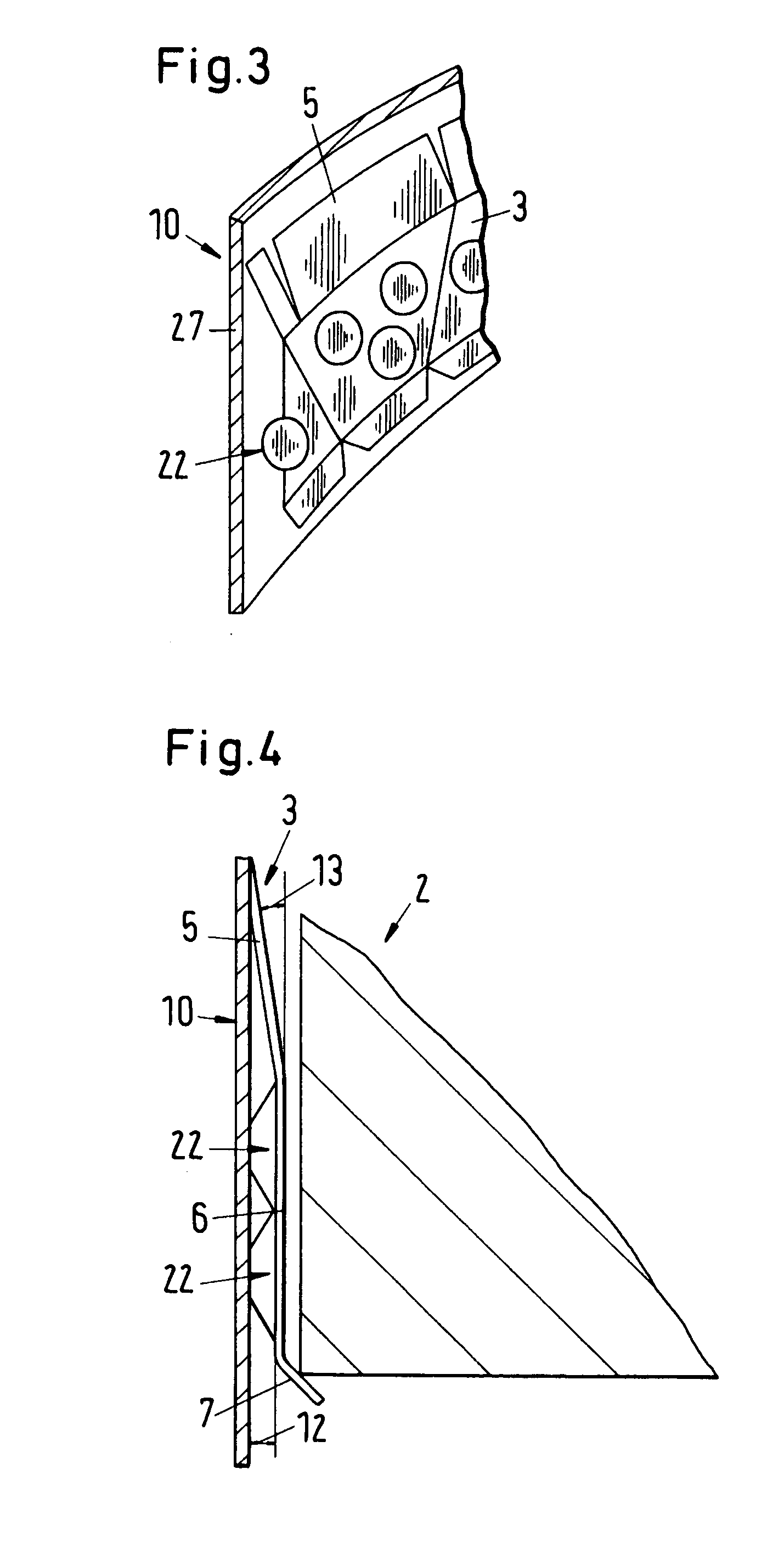
[0041]The wall element 6 can comprise a protrusion 16. Such a protrusion could be a rib extending essentially in parallel to the first and second bending lines, it can also comprise a plurality of bubble-like elements. The protrusion 16 serves in the assembled state of the crown element to keep a distance, the edge gap 12 between the column wall 10 as seen in FIG. 3 and the wall element 6.

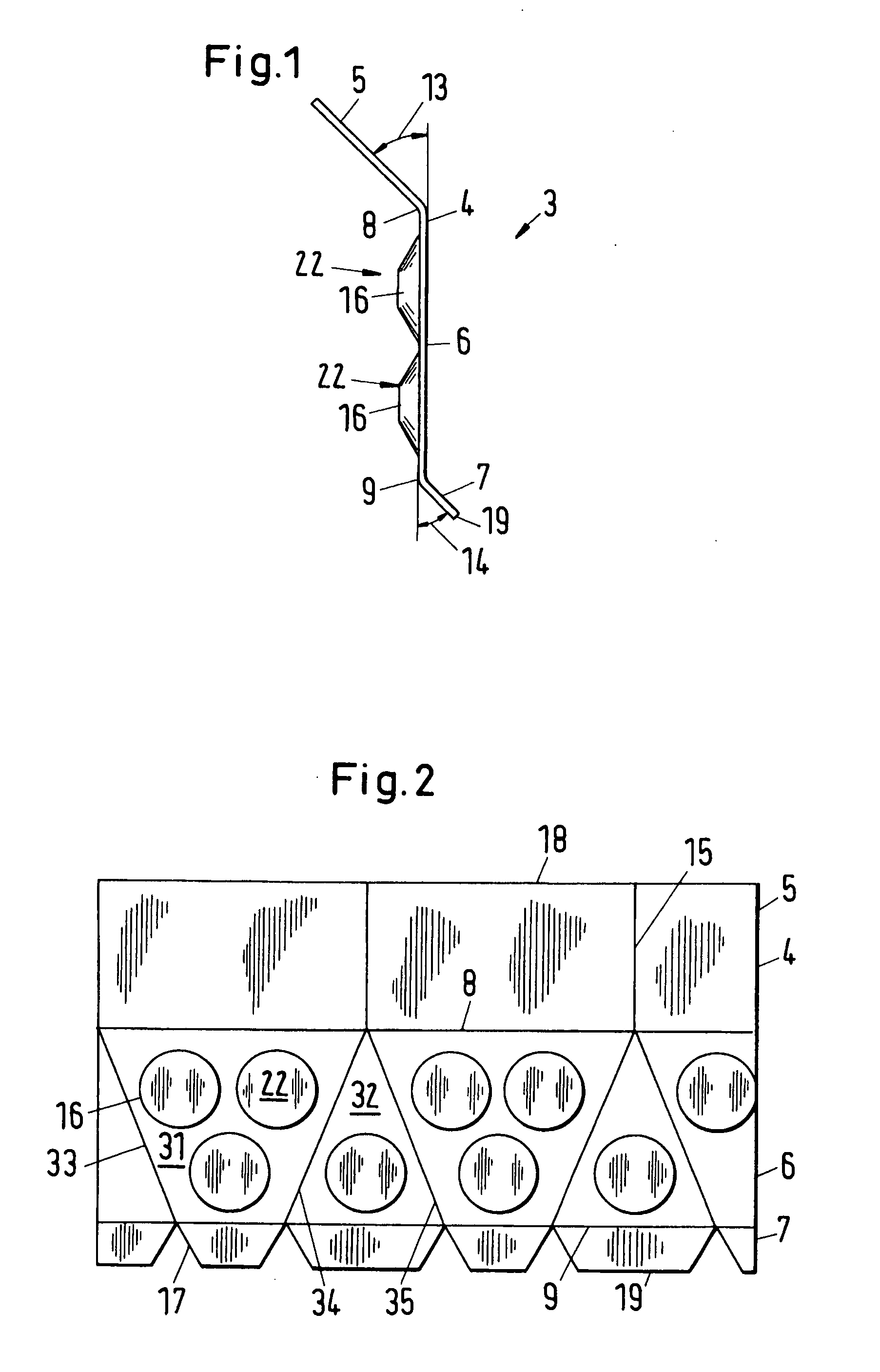
[0042]FIG. 2 is a front view of a portion of an elongate sheet 4 constituting a crown element according to FIG. 1....


PUM


Abstract

The crown element for securing a packing in a mass transfer column comprises an elongate sheet which comprises a roof element, a wall element and a bottom element. A first bending line is formed between the roof element and the wall element and a second bending line is formed between the wall element and the bottom element. Incisions are formed in the roof element and grooves are formed in the bottom element. The number of incisions is smaller than the number of grooves.

Description

[0001]This invention relates to a crown element for a packing of a mass transfer column. The invention also relates to a mass transfer column having crown elements for packings.BACKGROUND OF THE INVENTION[0002]The exchange part of a mass transfer column in which, in particular, an upwards flowing gas and a counter-flowing liquid are brought into contact, consists of a packing which fills the cross-section of the column out to an annular gap at the column wall. The crown elements which encircle the packing serve for the deflection of these flows of matter. The gas flow is forced into the packing by the crown elements; the gas is thereby impeded from partially flowing through along the region at the edge of the column without coming into contact with the liquid. The packing is in particular an ordered packing which brings about a distribution of the two flows of matter across the cross-section of the column. Such a crown element is for instance disclosed in U.S. Pat. No. 5,456,865 or ...

Claims


Application Information

Patent Timeline
Patent Type & Authority Applications(United States)
IPC IPC(8): F16M11/04F16M13/02
CPCB01J19/32B01J19/325Y10S261/72B01J2219/32275B01J2219/3221B01J19/24
Inventor KEHRER, FLORIANFLISCH, CURDIN
Owner SULZER MANAGEMENT AG
Why Eureka
Try Eureka