Unlock instant, AI-driven research and patent intelligence for your innovation.

Capacitive Measuring Circuit for Yarn Inspection

Inactive Publication Date: 2011-10-20
USTER TECHNOLOGIES
View PDF5 Cites 8 Cited by
  • Summary
  • Abstract
  • Description
  • Claims
  • Application Information

AI Technical Summary

Benefits of technology

[0008]The invention is based on the idea of enabling the change in the capacitance of at least one part of the measuring circuit with an electric control signal, without any mechanical or other interventions. This opens up the possibility for automatic balancing of the measuring circuit.
[0015]The invention is useful for balancing the measuring circuit. The balancing of the measuring circuit can occur in a simple, rapid and cost-effective way thanks to the invention. The device no longer needs to be opened in order to balance the measuring circuit. The balancing can be made at any time. It can automatically be made by the device itself without any intervention by an operator. This allows performing the balancing at any time. A balancing could be performed before each measurement with the measuring circuit, before every 10th measurement, or automatically after relevant changes of long-term properties of the output signal or after a larger change of the environmental conditions. This can lead to an increase in the precision, reliability and reproducibility of the measurement, and generally to an improvement in the results of the measurement.

Problems solved by technology

Due to the various imperfections in real electric components, it is not sufficient in practice to arrange the measuring circuit symmetrically in order to obtain a zero signal without the test material.
Such a manual balancing is laborious, time-consuming and expensive.

Method used


Image

  • Capacitive Measuring Circuit for Yarn Inspection
  • Capacitive Measuring Circuit for Yarn Inspection
  • Capacitive Measuring Circuit for Yarn Inspection

Examples


Embodiment Construction

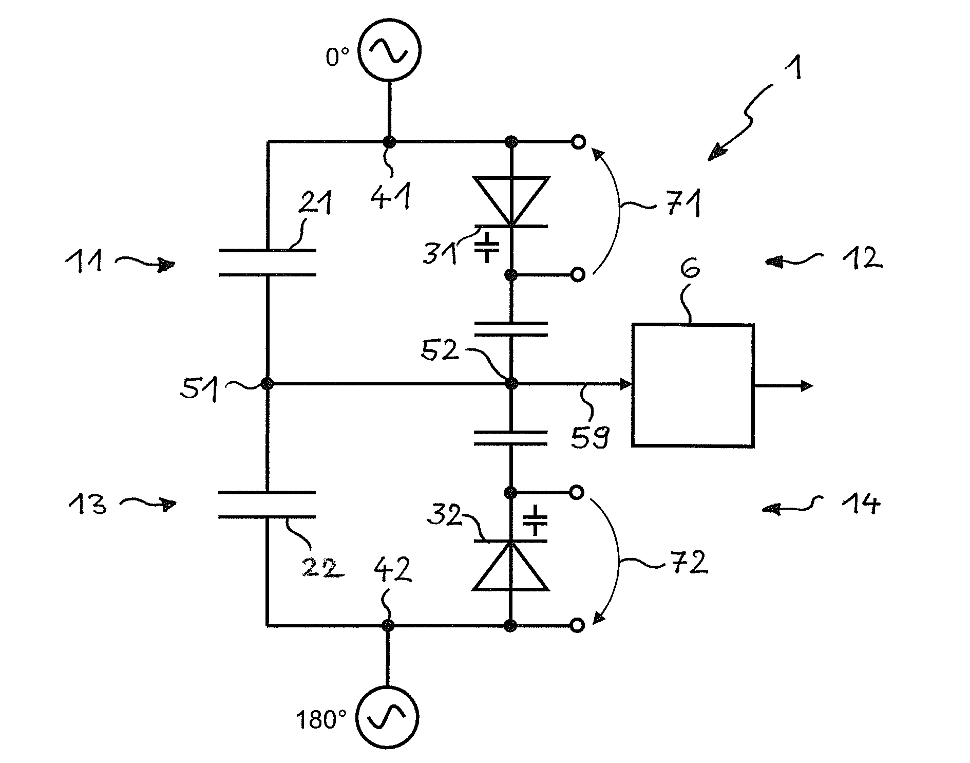
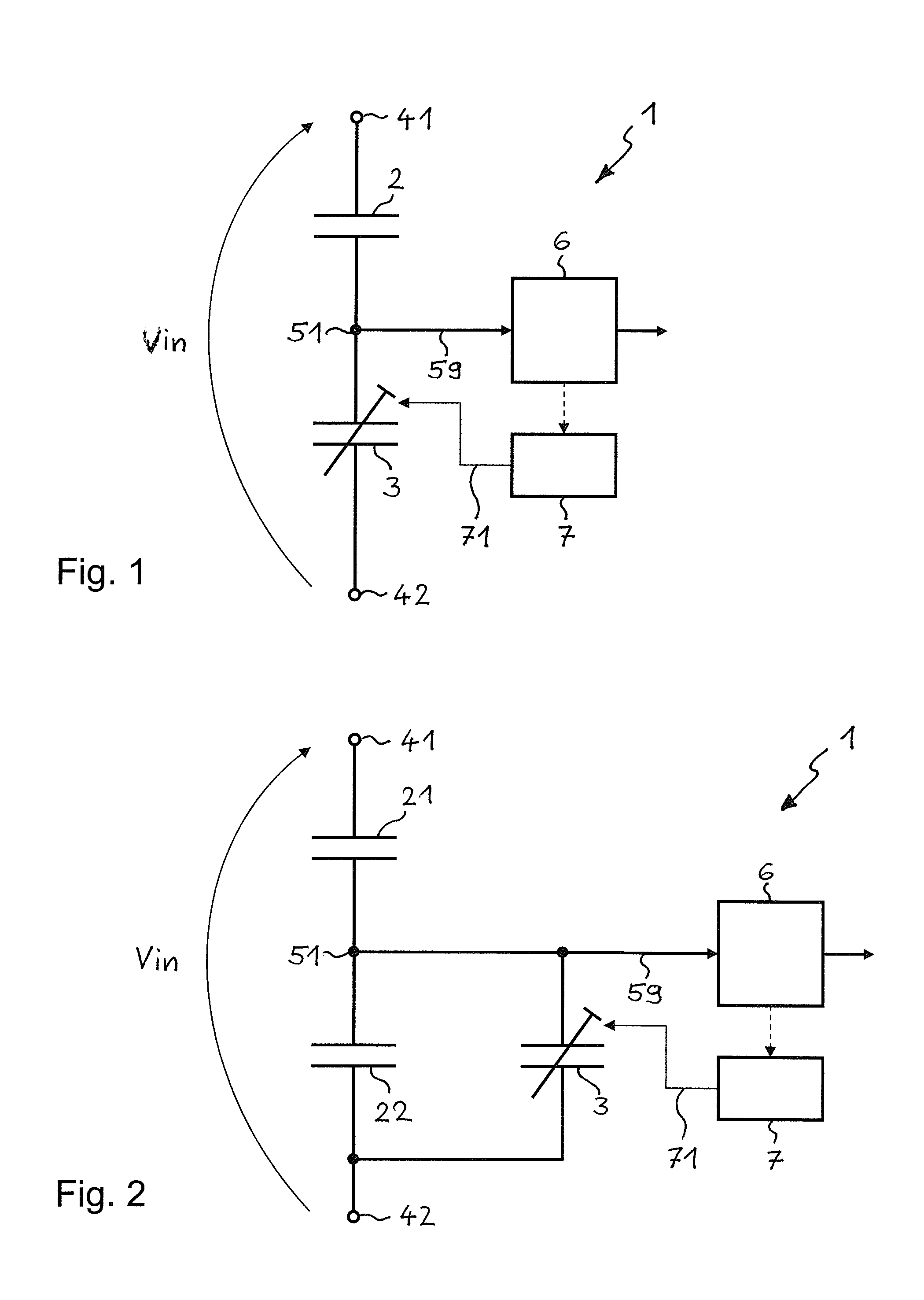
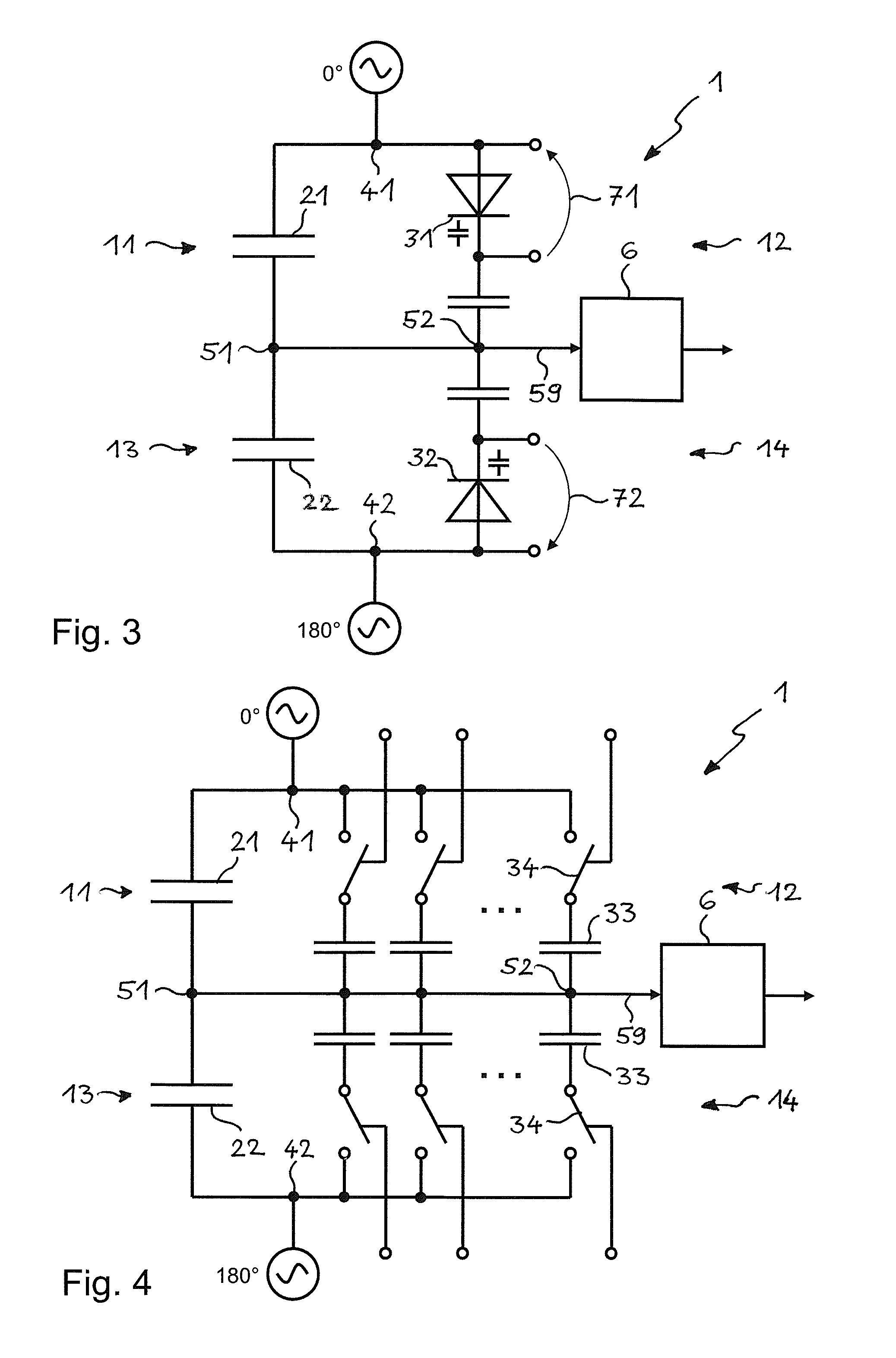
[0020]The circuit diagram of FIG. 1 shows the basic idea of the invention in a simple manner. A measuring circuit 1 contains a capacitance 2 to be measured and a capacitance 3 which is variable by an electric control signal 71. Possibilities for realizing the electrically variable capacitance 3 will be discussed in connection with FIGS. 3 to 5. The two capacitances 2, 3 are symbolized here schematically by capacitors. They are connected in series one behind the other in this embodiment. Two input connections 41, 42 for applying an electric alternating voltage signal Vin are disposed at the two ends of the series connection, to which measuring circuit 1 is connected. An output connection 51 for the output of an output signal of the measuring circuit 1 is disposed between the two capacitances 2, 3 connected in series. An output line 59 guides the output signal from the output connection 51 to an evaluation unit 6 for the purpose of evaluation.

[0021]During the balancing of the measurin...


PUM


Abstract

A measuring circuit used for the capacitive examination of a moving elongated textile test material such as card sliver, roving, yarn or woven fabric, having a measuring capacitor for accommodating the test material, and a component with a capacitance which can be changed by an electric control signal. The measuring circuit can thus be balanced in a simple, rapid, cost-effective and especially automatic way.

Description

BACKGROUND OF THE INVENTION[0001]The present invention lies in the field of the electric measuring circuits. It relates to a capacitive measuring circuit according to the preamble of the first claim and a method for operating a capacitive measuring circuit according to the preamble of a further independent claim. The invention allows automatic balancing of the measuring circuit, a simulation of measurements with the measuring circuit, a testing of the measuring circuit or a testing of components connected in series with the measuring circuit.[0002]A preferred field of application for the invention is the capacitive testing of elongated, preferably textile structures such as a card sliver, roving, yarn or woven fabric. The invention thus also relates to an apparatus for the capacitive examination of a moved elongated test material according to the preamble of a further claim. The goal of such an examination can be for example the detection of foreign substances, the recognition of ch...

Claims


Application Information

Patent Timeline
IPC IPC(8): G01R27/26
CPCG01N33/365G01N27/228G01R17/16G01N27/221G01N27/226
Inventor GEHRIG, RETOOTT, PHILLIPPJOSS, ROLF
Owner USTER TECHNOLOGIES