Elastic member structure of magnetic head

a technology of elastic member and magnetic head, which is applied in the direction of head, record information storage, instruments, etc., can solve the problems of affecting affecting the performance requiring more time and labor to remove screws or solders for maintenance, so as to improve the elastic member structure of the magnetic head, improve the connection of related components, and improve the effect of elastic member structur

Inactive Publication Date: 2011-10-20
CASTLES TECH
View PDF2 Cites 6 Cited by
  • Summary
  • Abstract
  • Description
  • Claims
  • Application Information

AI Technical Summary

Benefits of technology

[0011]The primary objective of the present invention is to provide an improved elastic member structure of a magnetic head that provides a secured connection of the elastic member and the magnetic head and simple and easy installation and removal by means of improving the connection of related components.
[0012]Another objective of the present invention is to provide an improved elastic member structure of a magnetic head that increases the stability of the structure to prevent any displacement or structural deformation when a card is read.
[0013]A further objective of the present invention is to provide an improved elastic member structure of a magnetic head that includes an engaging elastic member for stabilizing the pressure of connecting the magnetic head module to improve the card reading efficiency and prevent poor data reading.

Problems solved by technology

If the magnetic head and the magnetic strip are attached too closely or not closely enough, then the friction produced by sliding the magnetic strip through the magnetic head may damage the magnetic head and the magnetic strip easily or cause a failure of reading data.
Although the screw connection and soldering methods are simple, easily and cost saving, yet it takes more time and labor to remove the screws or the solder for maintaining, repairing or replacing the magnetic head or the elastic member of the magnetic head, and these are the major drawbacks of a fixed magnetic head.
Furthermore, the conventional way of fixing the elastic member of the magnetic head onto the base by the screw connection method usually produces non-uniform locking pressure and results in a poor reading of data or even a damage of components.

Method used


Image

  • Elastic member structure of magnetic head
  • Elastic member structure of magnetic head
  • Elastic member structure of magnetic head

Examples


Embodiment Construction

[0024]The structural assembly, overall operation and technical characteristics of the present invention will become apparent with the detailed description of the preferred embodiments and the illustration of the related drawings as follows.

[0025]To achieve the foregoing objectives and effects, the inventor of the present invention adopts a fixing base plate together with an elastic member of a magnetic head, and uses a passing and engaging method for connecting them, and constantly makes adjustments and corrections to obtain an improved elastic member structure of a magnetic head in accordance with the present invention. The overall structure and technical characteristics of an improved elastic member structure of a magnetic head in accordance with the present invention will be demonstrated by first and second preferred embodiments as follows.

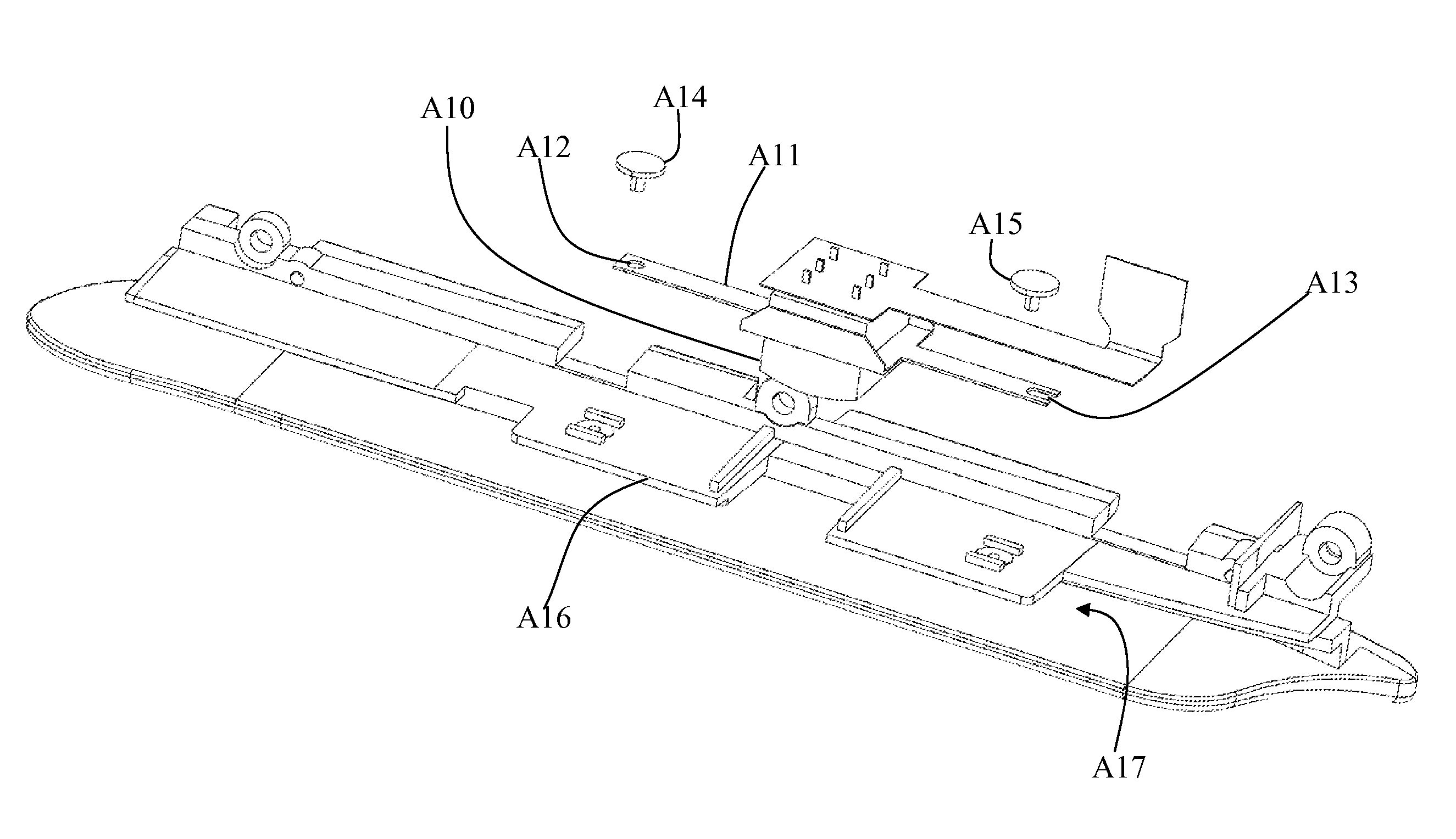
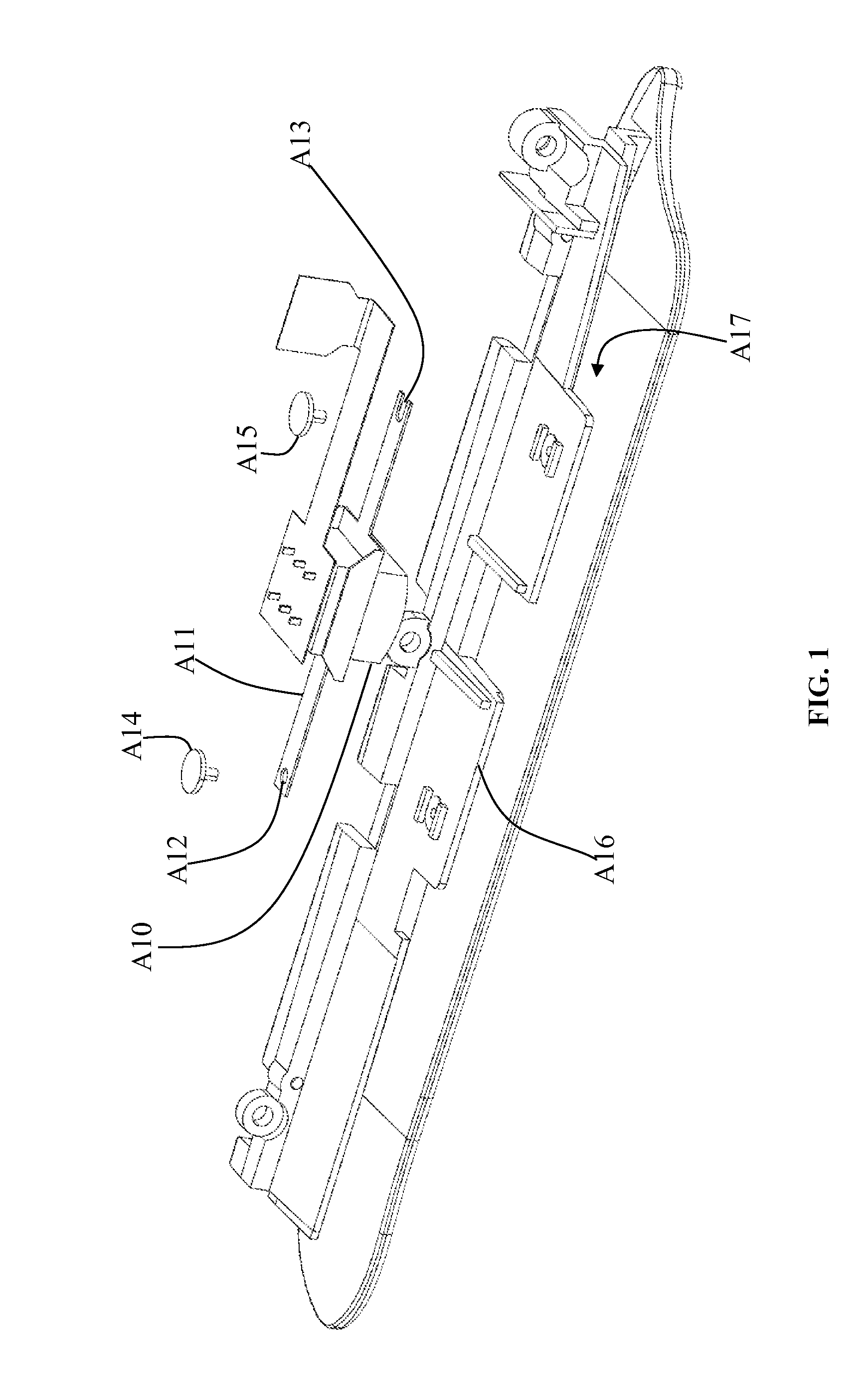
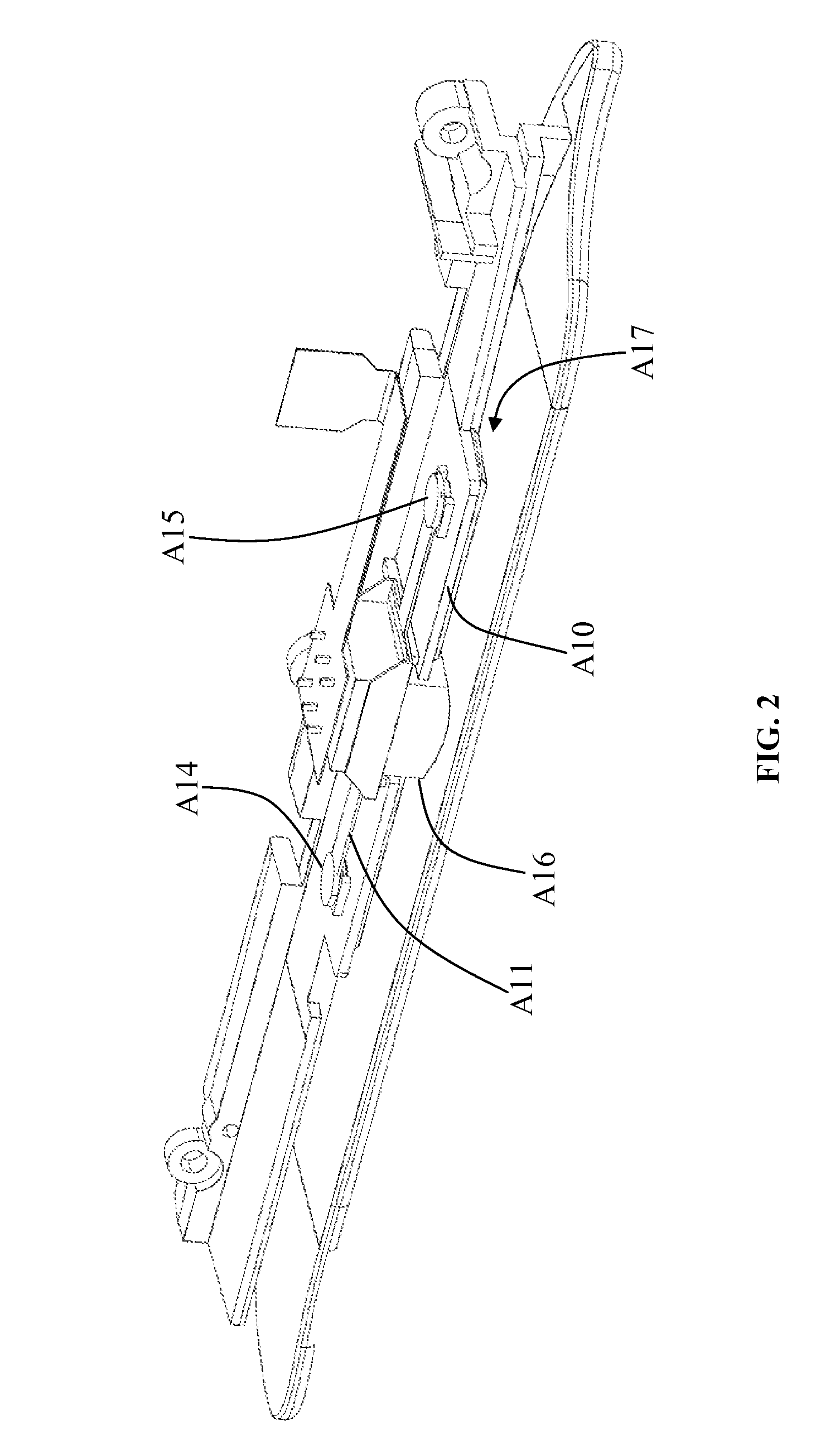
[0026]With reference to FIGS. 3 and 4 for an exploded view and a perspective view of an improved elastic member structure of a magnetic head i...


PUM

PropertyMeasurementUnit
elastic memberaaaaaaaaaa
sizeaaaaaaaaaa
elasticaaaaaaaaaa

Abstract

An improved elastic member structure of a magnetic head comprises: a base having a first and a second holder plates, a first through hole being formed on the first holder plate, and a gap being formed between the first and second holder plates; a fixing base plate being fixed onto the first holder plate and having a second through hole formed at the center, and the two sides of the second through hole comprising a third through hole respectively; an engaging elastic member being disposed onto the fixing base plate and having a fourth through hole formed at the center, and both ends of the engaging elastic member are passed through the third through holes respectively for fixing the engaging elastic member onto the fixed base plate; and a magnetic head module being passed into the first, second and fourth through holes for contacting a card and reading data.

Description

BACKGROUND OF THE INVENTION[0001]1. Field of the Invention[0002]The present invention relates to an elastic member structure of a magnetic head, and more particularly to an improved structure of a magnetic head with a fixing way.[0003]2. Description of the Related Art[0004]Using a magnetic card for a financial transaction such as making a payment or transferring money has become an integral part of our daily life. Other applications of the magnetic cards including door security control and personal identification are also used extensively, and thus a magnetic head fixing structure of a card reader for reading data from a magnetic strip of the magnetic card becomes more important as the scope of applicability of the magnetic card becomes broader.[0005]When a magnetic head of the card reader reads data from the magnetic strip, the magnetic head and the magnetic strip must be attached closely with each other before the magnetic head can read the data from the magnetic strip effectively...

Claims


Application Information

Patent Timeline
Patent Type & Authority Applications(United States)
IPC IPC(8): G11B5/48
CPCG06K7/084G11B5/488G11B5/00808
Inventor KUAN, CHUN-WEILO, YI-HSIUNGCHENG, KAI-YU
Owner CASTLES TECH
Why Eureka
Try Eureka