Methods of scatter correction of x-ray projection data 2

Active Publication Date: 2011-10-20
VARIAN MEDICAL SYSTEMS
View PDF3 Cites 13 Cited by
  • Summary
  • Abstract
  • Description
  • Claims
  • Application Information

AI Technical Summary

Problems solved by technology

However, the distribution of the radiation may be slightly non-uniform.
These scattered rays are often received by “surrounding” detector elements that are not located on the transmission path that the initial quantum of radiation was transmitted on, thereby creating measurement errors.
The measurement errors created by scattered radiation cause artifacts and loss of spatial and contrast resolution in the radiographic projection data and the CT images produced by the radiation imaging sys

Method used


Image

  • Methods of scatter correction of x-ray projection data 2
  • Methods of scatter correction of x-ray projection data 2
  • Methods of scatter correction of x-ray projection data 2

Examples


Embodiment Construction

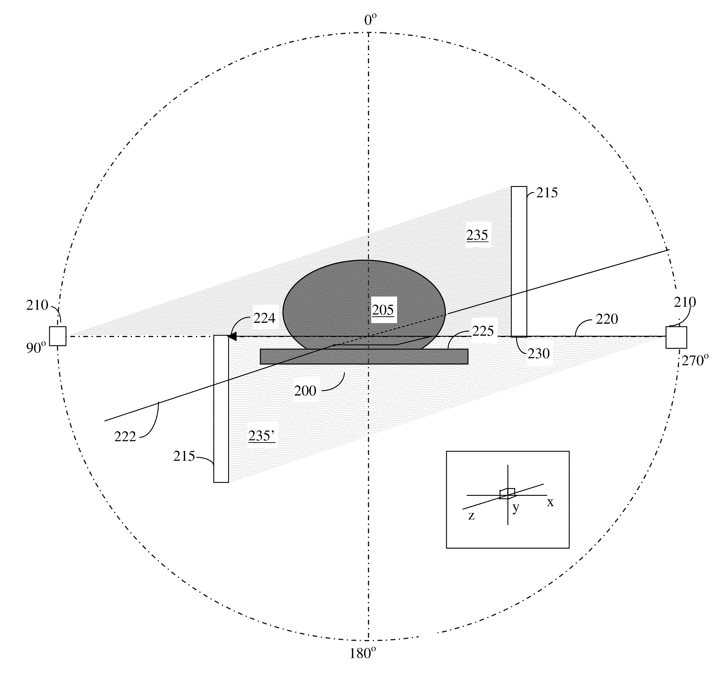
[0032]The inventive methods will be described according to embodiments addressing scattering from a scattering object adjacent to the target object or object of interest. An example thereof is a patient table which acts as a supporting structure for the object of interest. These embodiments are exemplary and not limiting. The methods and systems described herein can be applied to scattering from other objects adjacent to the object of interest.

[0033]The methods and associated systems and computer program products may be used alone or in various combinations with one another. As used herein and in the claims, the action of obtaining an item, such as an estimate of a quantity, encompasses the action of receiving the item from an outside process, computer-program product, and / or system, and the action of generating the item by the claimed process, computer-program product, or system.

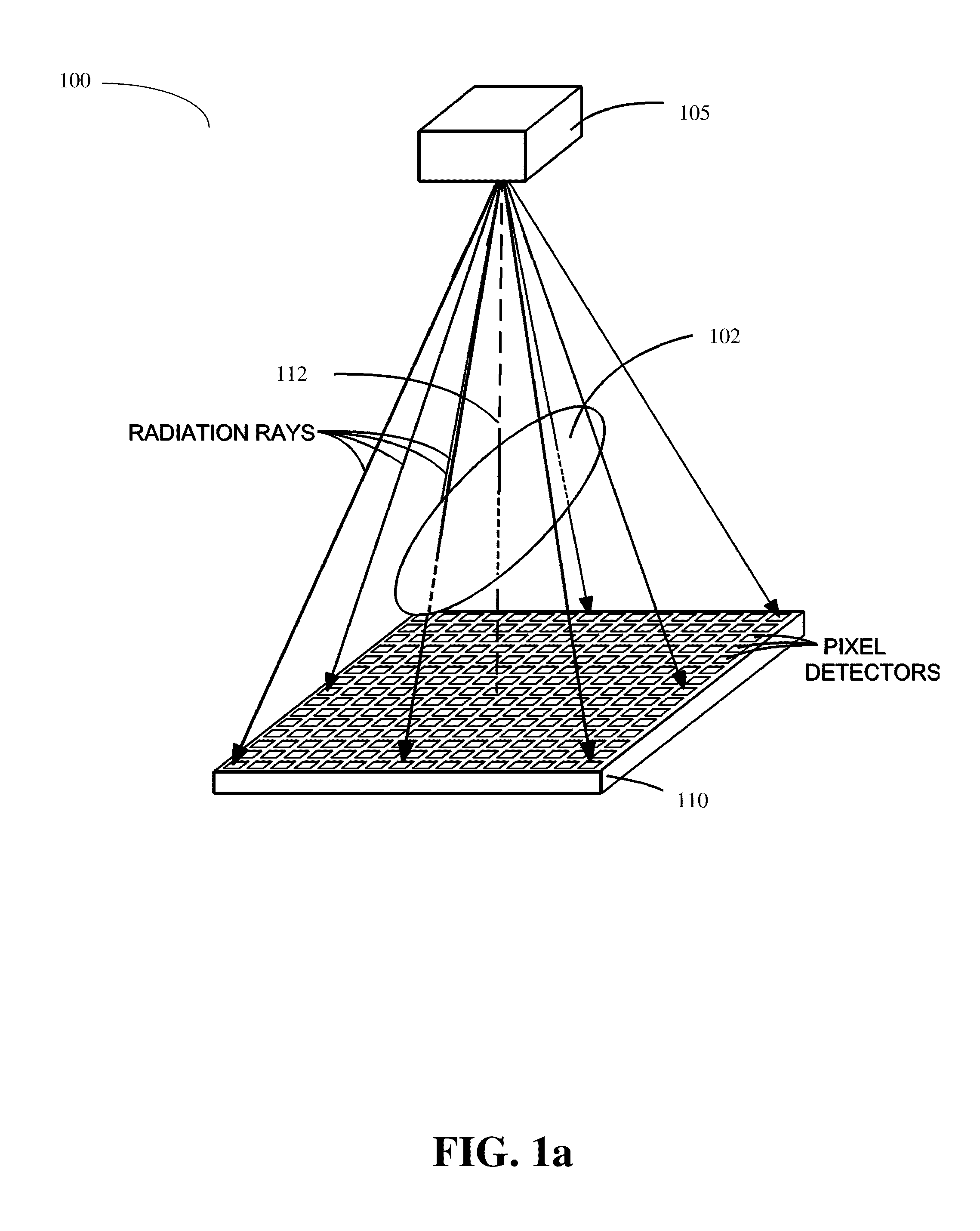
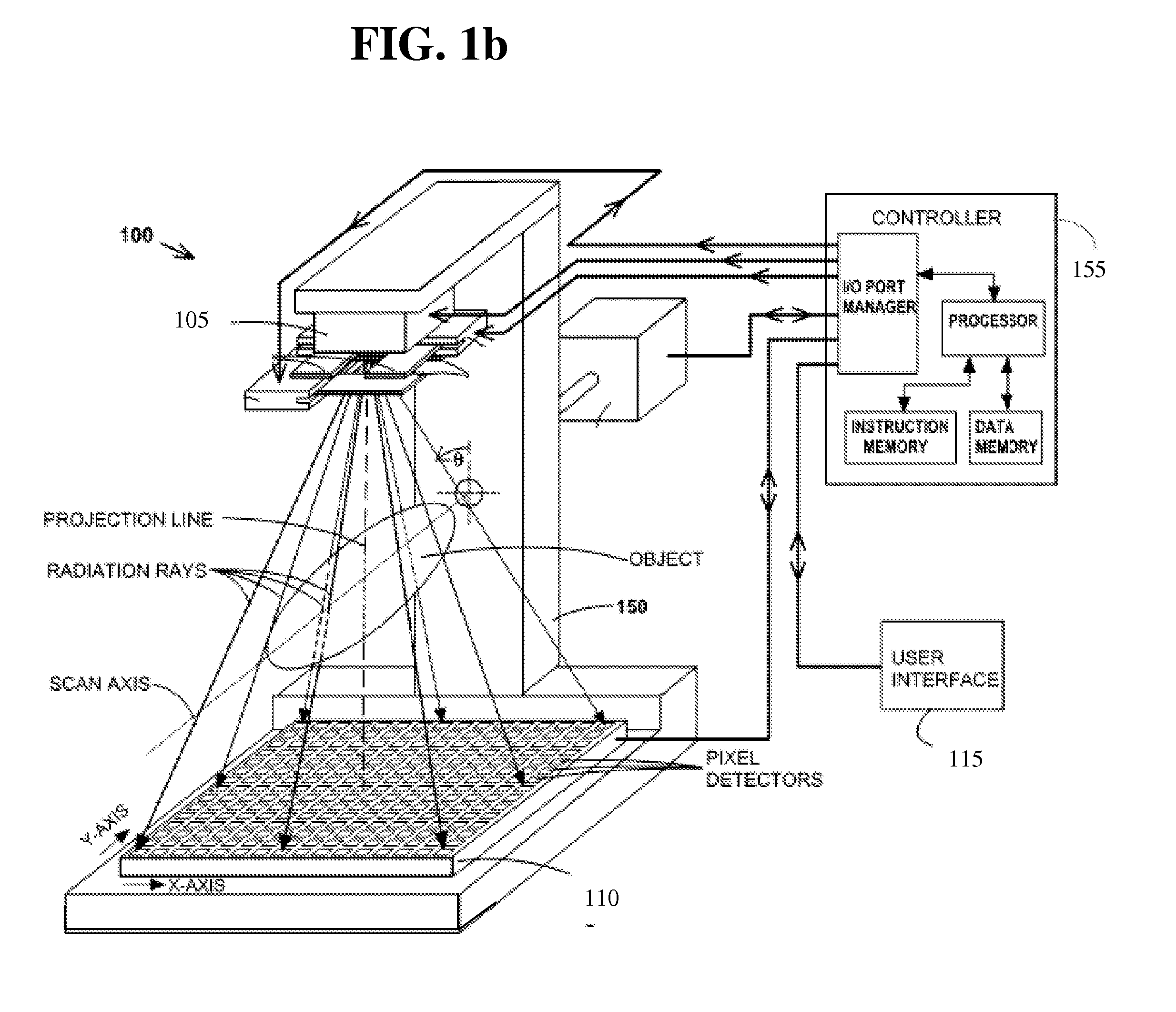
[0034]The radiographic projections described herein are generated by a two-dimensional imaging device ir...


PUM


Abstract

A system and method for forming an adjusted estimate of scattered radiation in a radiographic projection of a target object, which incorporates scattered radiation from objects adjacent to the target object, such as a patient table. A piercing point equalization method is disclosed, and a refinement of analytical kernel methods which utilizes hybrid kernels is also disclosed.

Description

CROSS REFERENCE TO RELATED APPLICATIONS[0001]This application is related to commonly owned U.S. patent application Ser. No. 12 / 125,053, filed on May 21, 2008. FIELD OF THE INVENTION[0002]This invention relates to the correction of the effects of scattered radiation on the x-ray radiographic projection of an object and in particular as applied to Computerized Tomography (CT).BACKGROUND[0003]Referring to FIGS. 1a and 1b, computerized tomography (CT) involves the imaging of the internal structure of an object 102 by collecting several projection images (“radiographic projections”) in a single scan operation (“scan”), and is widely used in the medical field to view the internal structure of selected portions of the human body. Typically, several two-dimensional projections are made of the object at different projection angles, and a three-dimensional representation of the object is constructed from the projections using various tomographic reconstruction methods. From the three-dimensio...

Claims


Application Information

Patent Timeline
IPC IPC(8): H05G1/60
CPCA61B6/5282A61B6/03G06T11/005A61B6/5205A61B6/032A61B6/0407
Inventor STAR-LACK, JOSHSUN, MINGSHAN
Owner VARIAN MEDICAL SYSTEMS
Why Eureka
Try Eureka