
Abrasive apparatus of a sander

Active Publication Date: 2011-10-20
KINGSAND MACHINERY
View PDF6 Cites 1 Cited by
  • Summary
  • Abstract
  • Description
  • Claims
  • Application Information

AI Technical Summary

Benefits of technology

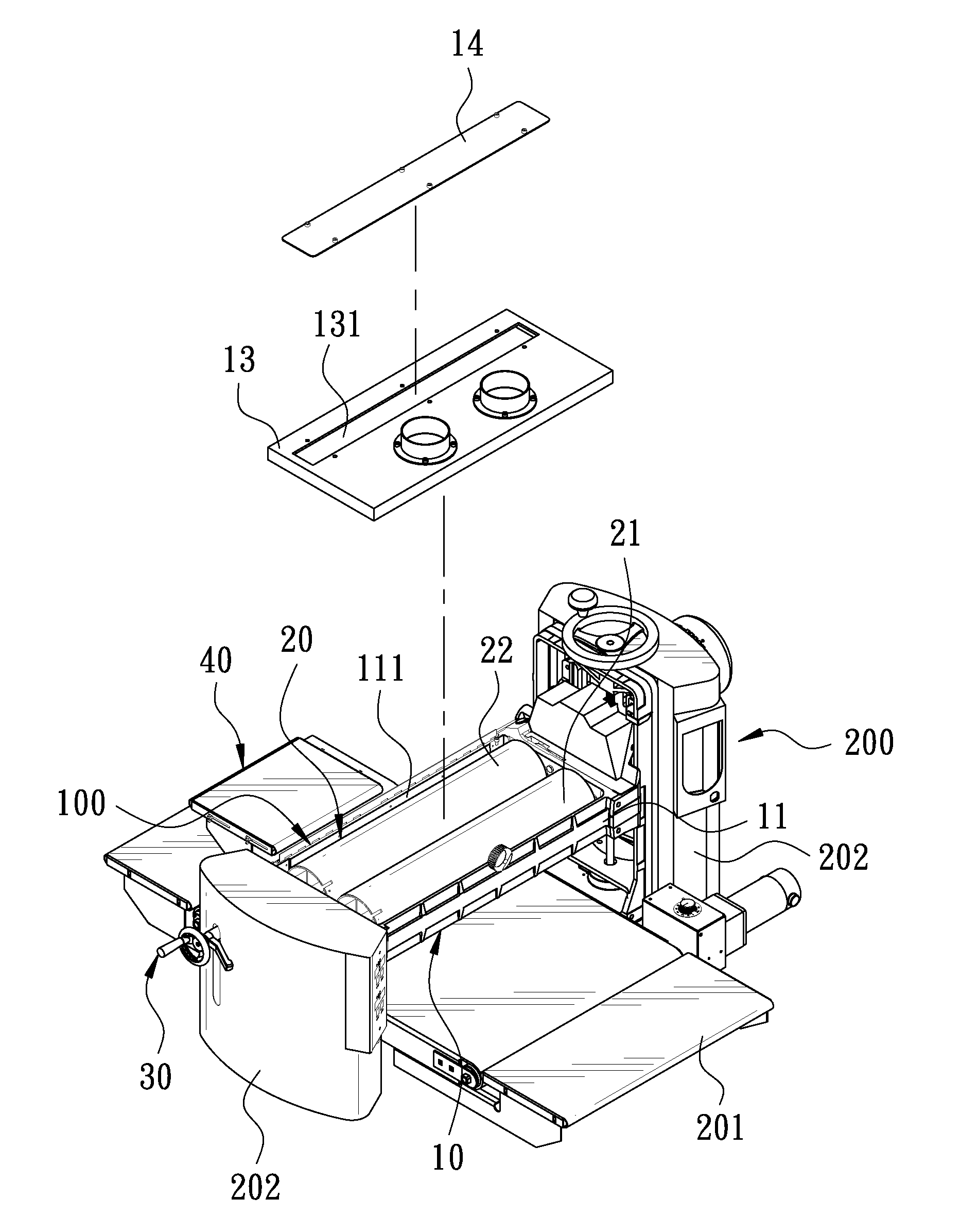
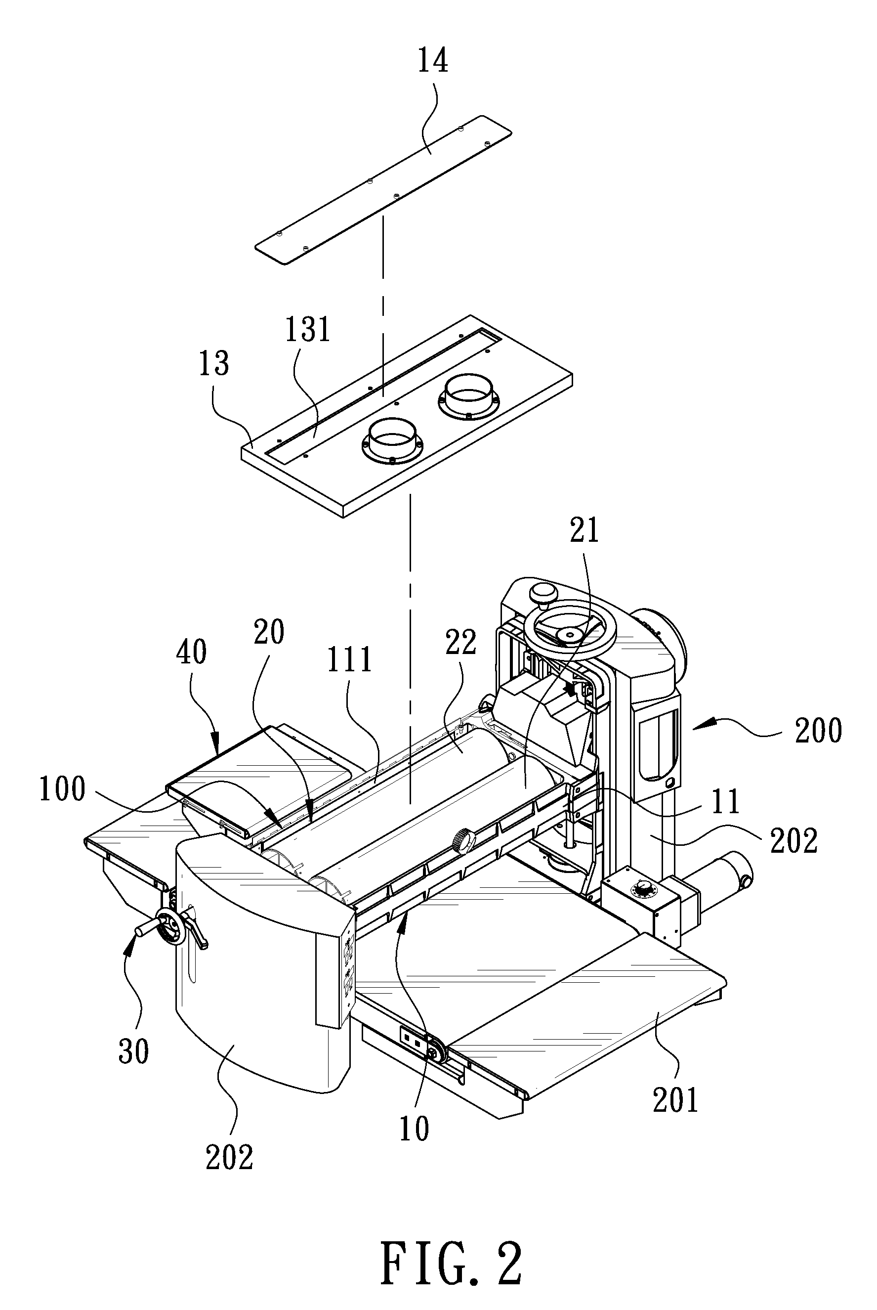
[0005]The present invention is to provide an abrasive apparatus of a sander. The abrasive apparatus is disposed above a worktable of the sander and includes a base and a lift unit. The base has an accommodation room therein and at least one abrasive wheel pivotally connected in the accommodation room. The base has a top formed with at least one slot. The slot communicates with the accommodation room. The lift unit is disposed on the abrasive wheel to bring the abrasive wheel to move up so that an abrasive surface of the abrasive wheel passes through the slot of the base and protrudes from the base for the top of the base to sand the top and the bottom of a workpiece. The side of the workpiece can be directly sanded on top of the base. The cutting width of the sander can be extended to enhance the use of the sander, so the manufacturing process can be shortened to increase the production efficiency and save the cost for the factory building.

Problems solved by technology

However, the height of adjustment between the abrasive apparatus 4 and the worktable 1 is limited.
Thus, the production cost is increased and the factory building needs more space and the production process is lengthened.

Method used


Image

  • Abrasive apparatus of a sander
  • Abrasive apparatus of a sander
  • Abrasive apparatus of a sander

Examples


Embodiment Construction

[0011]Embodiments of the present invention will now be described, by way of example only, with reference to the accompanying drawings.

[0012]As shown in FIGS. 2 to 4, an abrasive apparatus 100 according to a preferred embodiment of the present invention is mounted on a sander 200. The sander 200 comprises a worktable 201. The worktable 201 comprises a pair of slide seats 202 at two sides thereof. The abrasive apparatus 100 is disposed between the pair of slide seats 201. The abrasive apparatus 100 comprises a base 10, a lift unit 30, and a support platform 40.

[0013]The base 10 has an annular base body 11. The base body 11 has a pair of connection seats 12 at two sides thereof. The connection seats 211 are slidably connected to the slide seats 202. The base body 11 has an accommodation room 111 therein. An abrasive wheel 20 is pivotally connected in the accommodation room 111. In this embodiment, there are two abrasive wheels 20 in the accommodation room 111. The two abrasive wheels 2...


PUM


Abstract

An abrasive apparatus of a sander is provided. The abrasive apparatus is disposed above a worktable of the sander and includes a base and a lift unit. At least one abrasive wheel is provided in the base. The base has a top formed with at least one slot. The lift unit is disposed on the abrasive wheel to bring the abrasive wheel to move up so that an abrasive surface of the abrasive wheel passes through the slot of the base and protrudes from the base for the top of the base to sand the side of a workpiece. The cutting width of the sander can be extended to enhance the use of the sander, so the manufacturing process can be shortened to increase the production efficiency.

Description

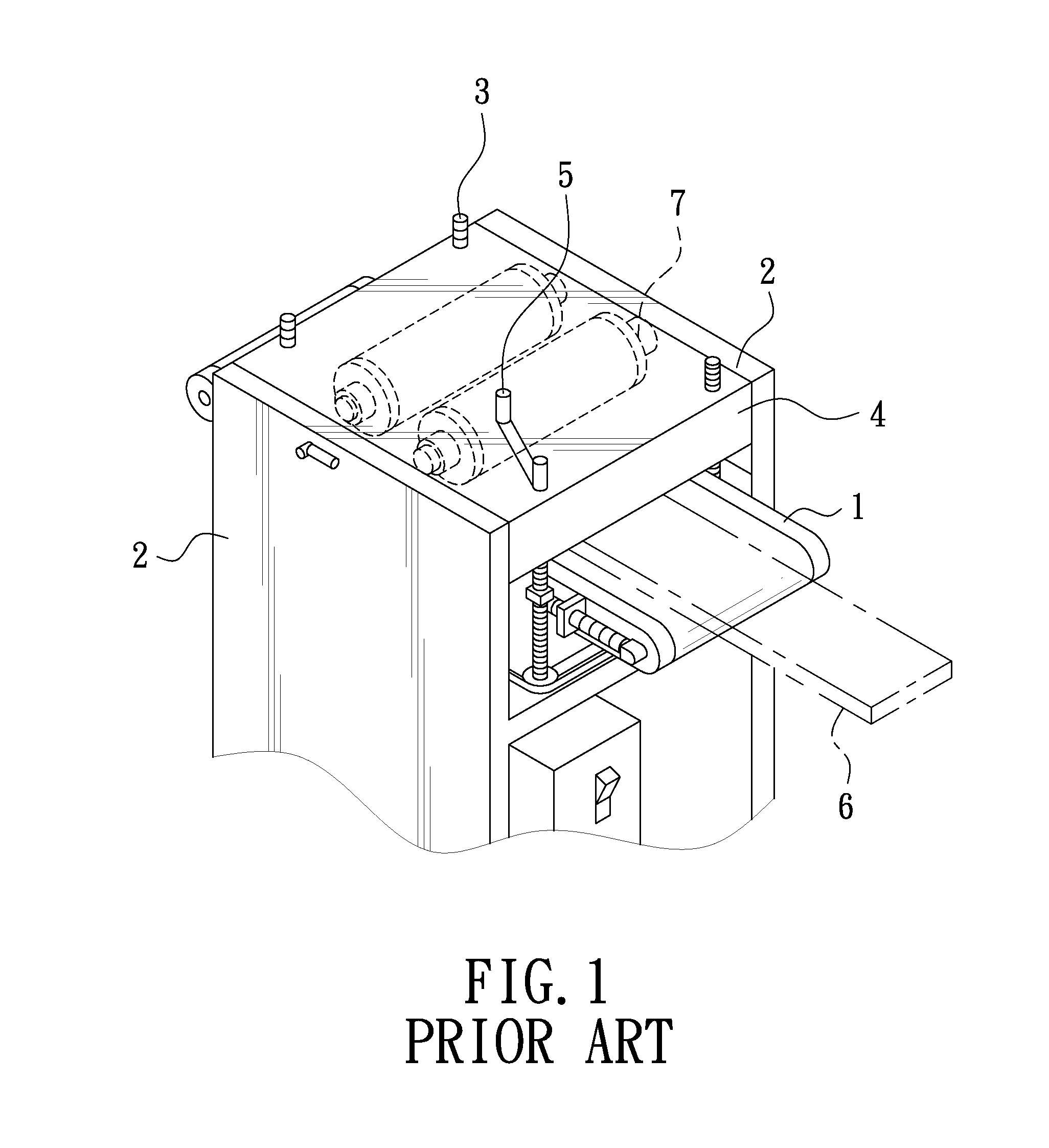
BACKGROUND OF THE INVENTION[0001]1. Field of the Invention[0002]The present invention relates to an abrasive apparatus of a sander.[0003]2. Description of the Prior Art[0004]As shown in FIG. 1, a conventional sander comprises a worktable 1. The worktable 1 comprises a pair of slide seats 2 at two sides thereof. The slide seats 2 are slidably connected to an abrasive apparatus 4 through four screws 3. The abrasive apparatus 4 is driven by a swing arm 5 which is connected to one of the screws 3 to move up or down within the slide seats 2, such that the abrasive position can be adjusted according to the thickness of a plank 6. However, the height of adjustment between the abrasive apparatus 4 and the worktable 1 is limited. If the plank 6 is too tall, the abrasive apparatus 4 can only sand the bottom and the top of the plank 6. The sides of the plank 6 can not be sanded by the abrasive apparatus 4 of the sander. It is necessary to use another apparatus, such as a trimmer, for a second ...

Claims


Application Information

Patent Timeline
IPC IPC(8): B24B41/00
CPCB24B7/075
Inventor CHANG, RICHARD
Owner KINGSAND MACHINERY
Learn More