Scheduling system and method

Active Publication Date: 2008-09-16
TEXAS INSTR INC
View PDF18 Cites 4 Cited by
  • Summary
  • Abstract
  • Description
  • Claims
  • Application Information

AI Technical Summary

Benefits of technology

[0008]This has advantages of simple but effe

Problems solved by technology

And the problem is to schedule the wafers for processing operations, typically in lots of 25 wafers which all receive identical processing, on the tools in the fab to maximize utilization of the tools.
Further, stochastic events such as tool breakdowns or varying lot priorities add to the scheduling complications.
A further complication of wafer fab scheduling arises from the simultaneous manufacture of several different integrated circuit products; each product has its own sequence of processing operation

Method used


Image

  • Scheduling system and method
  • Scheduling system and method
  • Scheduling system and method

Examples


Embodiment Construction

1. Overview

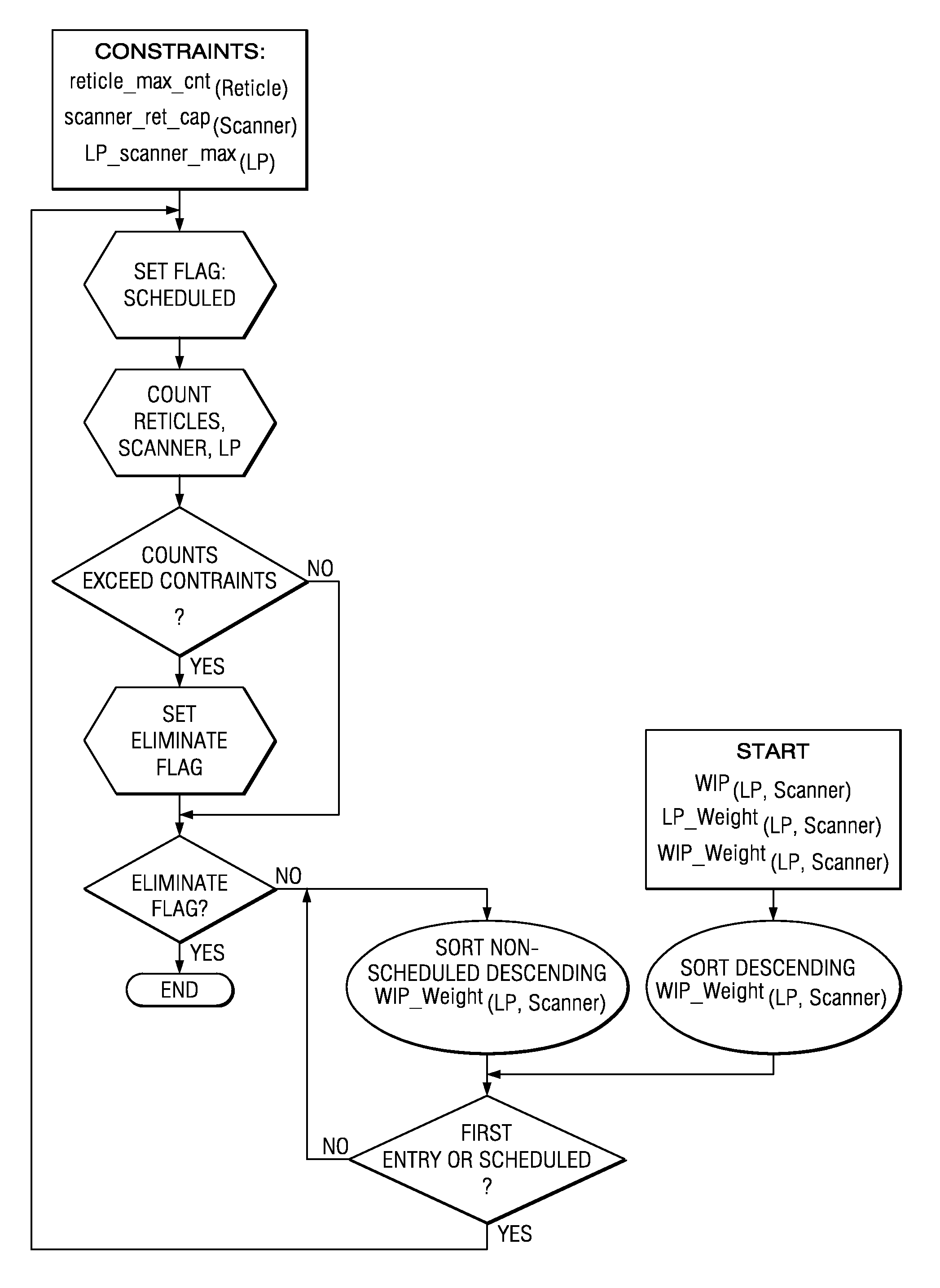
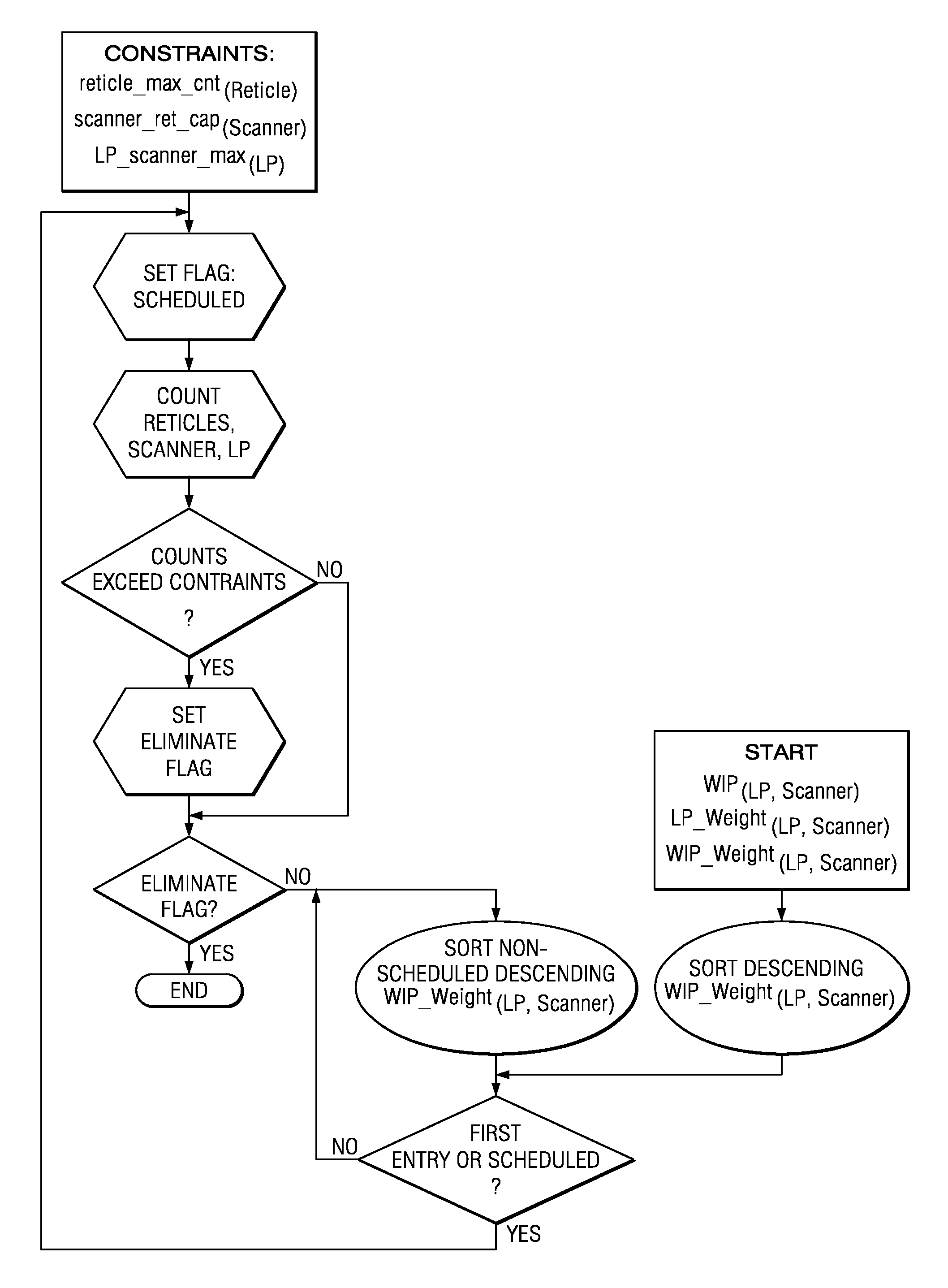
[0010]The preferred embodiment methods for a wafer fab solve the problem of which scanner (or stepper) runs which reticle while also managing current inventory and production line linearity. Managing reticles appropriately is extremely important in that tool time is not wasted while requisitioning a reticle from one scanner to another causing lost production opportunity. It is also important to maintain line linearity so that the utilization of the factory's other capital is maximized, but this must be balanced against current inventory at the scanners for cycle time considerations.

[0011]The preferred embodiment methods manage all three concerns and have demonstrated to perform at near optimality with minimal computational time making them very successful in making intelligent resource management decisions. The three preferred embodiment methods have differing emphases: The first places more emphasis on maintaining fab linearity, the second places the most emphasis on ret...


PUM


Abstract

Photolithography operation in a wafer fab using relative weightings of work in progress to iteratively schedule wafers.

Description

CROSS-REFERENCE TO RELATED APPLICATIONS[0001]This application claims priority from provisional applications: Ser. No. 60 / 403,089, filed Aug. 13, 2002. The following patent application discloses related subject matter: Appl. Ser. No. 10 / 352,653, filed Jan. 28, 2003. This referenced application has a common assignee with the present application.BACKGROUND OF THE INVENTION[0002]The invention relates to semiconductor device manufacturing, and more particularly to scheduling photolithography in a wafer fab.[0003]The manufacture of integrated circuit products typically involves hundreds of processing steps applied to a semiconductor (e.g., silicon) wafer over several weeks. Indeed, a typical wafer fab may at any time contain 50,000 wafers as work in progress and with a 20,000 wafer turnover per month. The basic processing operations in a wafer fab are photolithography, etching-polishing, deposition, implantation, oxidation, and diffusion-anneal plus various cleanings and inspections-measu...

Claims


Application Information

Patent Timeline
IPC IPC(8): G06F19/00G05B19/418G06F9/46G06Q10/04G06Q10/06G06Q10/08G06Q20/20
CPCG05B19/41865G06Q20/203G06Q10/0631G06Q10/087G06Q10/04G05B2219/32258G05B2219/32263Y02P90/02
Inventor HESKIN, JAMESSHEPHEARD, MARKLAFOY, JULIA
Owner TEXAS INSTR INC
Why Eureka
Try Eureka